CRAWL SWITCH INSPECTION
PROCEDURE
-
INSPECT CRAWL CONTROL SWITCH
-
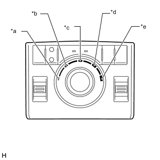
Text in Illustration *a LO *b LO / MEDIUM *c MEDIUM *d MEDIUM / HI *e HI 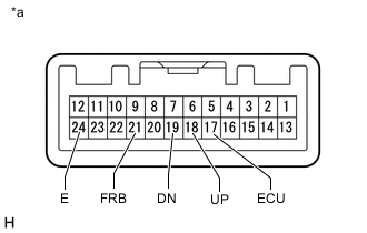
Text in Illustration *a Component without harness connected
(Center Cluster Module switch (Crawl Control Switch))
Measure the resistance according to the value(s) in the table below.
Standard Resistance Tester Connection Switch Condition Specified Condition 17 (ECU) - 24 (E) LO Below 1 Ω 18 (UP) - 24 (E) 19 (DN) - 24 (E) 10 kΩ or higher 17 (ECU) - 24 (E) LO / MEDIUM Below 1 Ω 18 (UP) - 24 (E) 10 kΩ or higher 19 (DN) - 24 (E) 17 (ECU) - 24 (E) MEDIUM 10 kΩ or higher 18 (UP) - 24 (E) 19 (DN) - 24 (E) 17 (ECU) - 24 (E) MEDIUM / HI 10 kΩ or higher 18 (UP) - 24 (E) 19 (DN) - 24 (E) Below 1 Ω 17 (ECU) - 24 (E) HI 10 kΩ or higher 18 (UP) - 24 (E) Below 1 Ω 19 (DN) - 24 (E) 21 (FRB) - 24 (E) ON/OFF: Pressed Below 1 Ω ON/OFF: Not pressed 10 kΩ or higher If the result is not as specified, replace the crawl control switch.
-