FRONT SPEED SENSOR INSTALLATION
CAUTION / NOTICE / HINT
Tech Tips
-
The procedure listed below is for the LH side.
-
Other than areas where instructions are provided, use the same procedures for the RH and LH sides.
PROCEDURE
-
INSTALL FRONT SPEED SENSOR LH
-
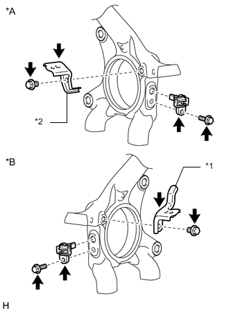
*A for LH *B for RH *1 No. 1 Skid Control Sensor Clamp *2 No. 2 Skid Control Sensor Clamp Install the front speed sensor LH with the bolt.
- Torque:
- 8.5 N*m { 87 kgf*cm, 75 in.*lbf }
Note
-
Make sure there are no pieces of iron or other foreign matter attached to the front speed sensor LH tip.
-
While inserting the front speed sensor LH into the knuckle hole, do not strike or damage the sensor tip.
-
After installing the front speed sensor LH, make sure there is no clearance or foreign matter between the front speed sensor LH stay part and the knuckle.
-
Make sure there is no foreign matter attached to the speed sensor rotor.
-
-
INSTALL FRONT SPEED SENSOR RH
Tech Tips
Use the same procedure described for the LH side.
-
INSTALL SKID CONTROL SENSOR CLAMP
-
for LH:
Install the No. 2 skid control sensor clamp with the bolt.
- Torque:
- 12.5 N*m { 127 kgf*cm, 9 ft.*lbf }
Note
Install the clamp so that the rotation stopper touches the knuckle.
-
for RH:
Install the No. 1 skid control sensor clamp with the bolt.
- Torque:
- 12.5 N*m { 127 kgf*cm, 9 ft.*lbf }
Note
Install the clamp so that the rotation stopper touches the knuckle.
-
-
INSTALL SKID CONTROL SENSOR WIRE (except 1GD-FTV)
-
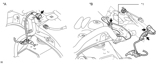
Connect the connector as follows.
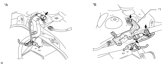
*A for LH *B for RH *1 NO. 3 SKID CONTROL SENSOR CLAMP - -
-
for LH:
1. Attach the connector, and then connect the connector.
Note
-
Securely connect the connector.
-
When connecting the connector, do not twist the wire harness.
-
-
for RH:
1. Install the No. 3 skid control sensor clamp with the bolt.
- Torque:
- 5.0 N*m { 51 kgf*cm, 44 in.*lbf }
Note
Make sure the clamp rotation stopper touches the installation position.
2. Attach the connector, and then connect the connector.
Note
-
Securely connect the connector.
-
When connecting the connector, do not twist the wire harness.
3. Attach the clip.
-
-
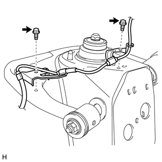
Install the 2 harness clamps with the 2 bolts.
- Torque:
- 12.5 N*m { 127 kgf*cm, 9 ft.*lbf }
Note
-
When installing the clamps, do not twist the wire harness.
-
Make sure the clamp rotation stopper touches the installation position.
-
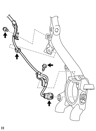
Install the 2 harness clamps with the 2 bolts.
- Torque:
- 12.5 N*m { 127 kgf*cm, 9 ft.*lbf }
Note
-
When installing the clamps, do not twist the wire harness.
-
Make sure the clamp rotation stopper touches the installation position.
-
Attach the clip.
-
Connect the connector.
Note
Securely connect the connector.
-
-
INSTALL SKID CONTROL SENSOR WIRE (for 1GD-FTV)
-
Connect the connector as follows.
*A for LH *B for RH *1 NO. 3 SKID CONTROL SENSOR CLAMP - -
-
for LH:
-
Attach the connector, and then connect the connector.
Note
-
Securely connect the connector.
-
When connecting the connector, do not twist the wire harness.
-
-
-
for RH:
-
Install the No. 3 skid control sensor clamp with the bolt.
Torque 5.0 N*m (51 kgf*cm, 44 in.*lbf) Note
Make sure the clamp rotation stopper touches the installation position.
-
Attach the connector clamp, and then connect the connector.
-
Attach the 2 clips.
-
-
-
Install the 2 harness clamps with the 2 bolts.
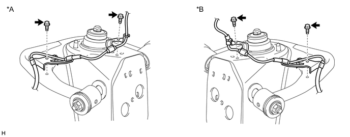
*A for LH *B for RH - Torque:
- 12.5 N*m { 127 kgf*cm, 9 ft.*lbf }
Note
-
When installing the clamps, do not twist the wire harness.
-
Make sure the clamp rotation stopper touches the installation position.
-
Install the 2 harness clamps with the 2 bolts.
- Torque:
- 12.5 N*m { 127 kgf*cm, 9 ft.*lbf }
Note
-
When installing the clamps, do not twist the wire harness.
-
Make sure the clamp rotation stopper touches the installation position.
-
Attach the clip.
-
Connect the connector.
Note
Securely connect the connector.
-
-
INSTALL FRONT WHEEL
- Torque:
- for Aluminum Wheel
- 103 N*m { 1050 kgf*cm, 76 ft.*lbf }
- for Steel Wheel
- 112 N*m { 1137 kgf*cm, 82 ft.*lbf }
-
CHECK SPEED SENSOR SIGNAL
-
w/o VSC:
Check the speed sensor signal Click here.
-
w/ VSC (for hydraulic brake booster):
Check the speed sensor signal Click here.
-
w/ VSC (for vacuum brake booster):
Check the speed sensor signal Click here.
-