TRIP SWITCH INSPECTION
PROCEDURE
-
INSPECT TRIP SWITCH (w/o TAIL Cancel Switch)
-
Inspect the light control rheostat.
-
Measure the resistance according to the value(s) in the table below.
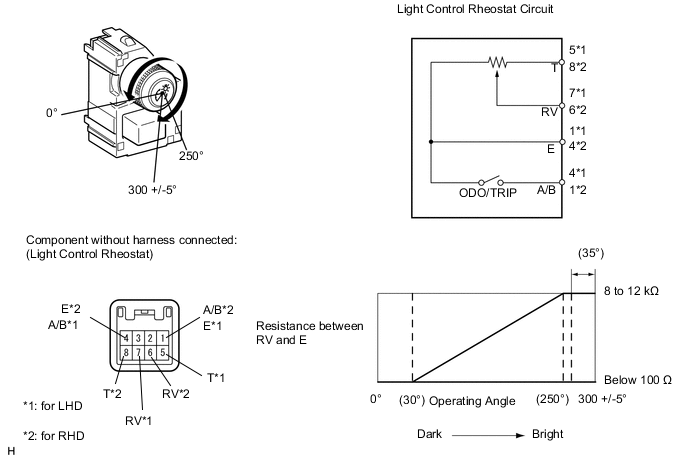
Standard Resistance for LHD Tester Connection Switch Condition Specified Condition 5 (T) - 1 (E) Always 8 to 12 kΩ 7 (RV) - 1 (E) Light control rheostat fully turned right → Light control rheostat fully turned left Below 100 Ω → 8 to 12 kΩ for RHD Tester Connection Switch Condition Specified Condition 8 (T) - 4 (E) Always 8 to 12 kΩ 6 (RV) - 4 (E) Light control rheostat fully turned right → Light control rheostat fully turned left Below 100 Ω → 8 to 12 kΩ
-
-
Inspect the ODO/TRIP switch.
-
Measure the resistance according to the value(s) in the table below.
Standard Resistance for LHD Tester Connection Switch Condition Specified Condition 4 (A/B) - 1 (E) ODO/TRIP switch on (Pushed) Below 1 Ω ODO/TRIP switch off (Not pushed) 1 MΩ or higher for RHD Tester Connection Switch Condition Specified Condition 1 (A/B) - 4 (E) ODO/TRIP switch on (Pushed) Below 1 Ω ODO/TRIP switch off (Not pushed) 1 MΩ or higher If the result is not as specified, replace the rheostat.
-
-
-
INSPECT TRIP SWITCH (w/ TAIL Cancel Switch)
-
Inspect the light control rheostat.
-
Measure the resistance according to the value(s) in the table below.
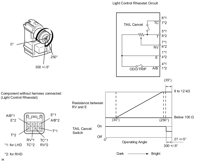
Standard Resistance for LHD Tester Connection Switch Condition Specified Condition 5 (T) - 6 (TC) TAIL cancel switch off → on 1 MΩ or higher → Below 100 Ω 5 (T) - 1 (E) Always 8 to 12 kΩ 7 (RV) - 1 (E) Light control rheostat fully turned right → Light control rheostat fully turned left Below 100 Ω → 8 to 12 kΩ for RHD Tester Connection Switch Condition Specified Condition 7 (TC) - 8 (T) TAIL cancel switch off → on 1 MΩ or higher → Below 1 Ω 8 (T) - 4 (E) Always 8 to 12 kΩ 6 (RV) - 4 (E) Light control rheostat fully turned right → Light control rheostat fully turned left Below 100 Ω → 8 to 12 kΩ
-
-
Inspect the ODO/TRIP switch.
-
Measure the resistance according to the value(s) in the table below.
Standard Resistance for LHD Tester Connection Switch Condition Specified Condition 4 (A/B) - 1 (E) ODO/TRIP switch on (Pushed) Below 1 Ω ODO/TRIP switch off (Not pushed) 1 MΩ or higher for RHD Tester Connection Switch Condition Specified Condition 1 (A/B) - 4 (E) ODO/TRIP switch on (Pushed) Below 1 Ω ODO/TRIP switch off (Not pushed) 1 MΩ or higher If the result is not as specified, replace the rheostat.
-
-