COMBINATION METER REMOVAL
CAUTION / NOTICE / HINT
Tech Tips
-
Use the same procedure for RHD and LHD vehicles.
-
The procedure listed below is for LHD vehicles.
PROCEDURE
-
DISABLE AUTOAWAY/RETURN FUNCTION (for Power Tilt and Power Telescopic Steering Column)
-
Disable the Autoaway/Return function by changing the customize parameter.
Note
Record the current customize parameter setting (whether the Autoaway/Return function is enabled or disabled) in order to restore the current setting after finishing the operation.
Tech Tips
Performing the above operation causes the Autoaway/Return function to be disabled when the ignition switch is turned off.
-
Turn the ignition switch to ON. Operate the tilt and telescopic switch to fully extend and lower the steering column.
-
Turn the ignition switch off.
-
-
PRECAUTION
Note
After turning the ignition switch off, waiting time may be required before disconnecting the cable from the battery terminal. Therefore, make sure to read the disconnecting the cable from the battery terminal notice before proceeding with work.
-
DISCONNECT CABLE FROM NEGATIVE BATTERY TERMINAL
CAUTION:
Wait at least 90 seconds after disconnecting the cable from the negative (-) battery terminal to disable the SRS system.
Note
When disconnecting the cable, some systems need to be initialized after the cable is reconnected.
-
REMOVE INSTRUMENT CLUSTER FINISH PANEL ORNAMENT (for LHD)
-
REMOVE INSTRUMENT PANEL FINISH PLATE GARNISH (for RHD)
-
REMOVE LOWER INSTRUMENT PANEL FINISH PANEL ASSEMBLY
-
REMOVE INSTRUMENT CLUSTER FINISH PANEL SUB-ASSEMBLY
-
except 5L-E:
-
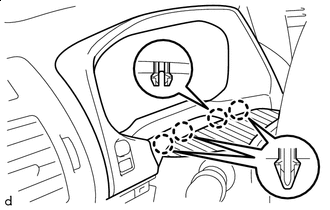

Protective Tape Place protective tape as shown in the illustration.
-
Detach the 4 claws.
-
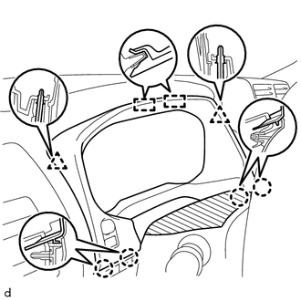
Detach the 4 claws.
-
Detach the 2 clips and 2 guides.
-
Disconnect the connector and remove the instrument cluster finish panel sub-assembly.
-
-
for 5L-E:
-
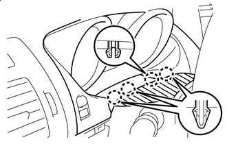
Protective Tape Place protective tape as shown in the illustration.
-
Detach the 4 claws.
-
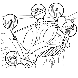
Detach the 4 claws.
-
Detach the 2 clips and 2 guides.
-
Disconnect the connector and remove the instrument cluster finish panel sub-assembly.
-
-
-
REMOVE COMBINATION METER ASSEMBLY
-
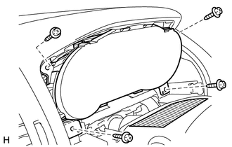
Remove the 4 screws and combination meter assembly.
-
Disconnect the 2 connectors.
-