VEHICLE STABILITY CONTROL SYSTEM(for Vacuum Brake Booster) Slip Indicator Light Remains ON
DESCRIPTION
The skid control ECU (brake actuator assembly) is connected to the combination meter assembly via CAN communication.
The slip indicator light blinks during VSC and/or TRC operation.
When the system fails, the slip indicator light comes on to warn the driver.
WIRING DIAGRAM
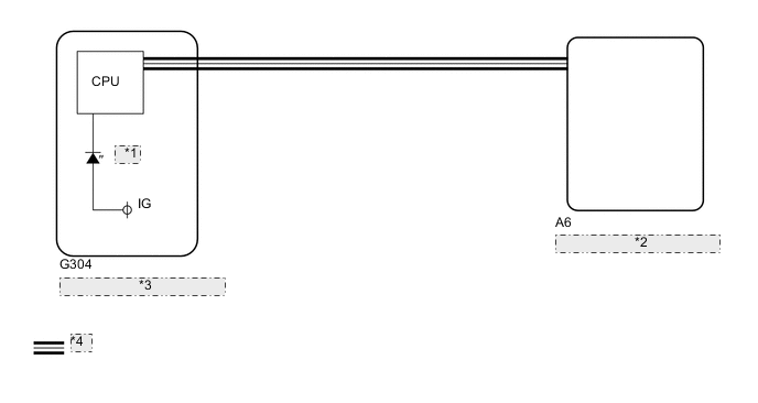
| *1 | Slip |
| *2 | Skid Control ECU (Brake Actuator Assembly) |
| *3 | Combination Meter Assembly |
| *4 | CAN Communication System |
CAUTION / NOTICE / HINT
Note
When replacing the skid control ECU (brake actuator assembly), perform calibration Click here.
PROCEDURE
-
CHECK CAN COMMUNICATION SYSTEM
-
Check if CAN communication system DTCs are output Click here
Result Result Proceed to DTC not output A DTC output B
B 
GO TO CAN COMMUNICATION SYSTEM (HOW TO PROCEED WITH TROUBLESHOOTING) Click here
A 
-
-
READ VALUE USING GTS (SLIP INDICATOR LIGHT)
-
Turn the ignition switch off.
-
Connect the GTS to the DLC3.
-
Turn the ignition switch to ON.
-
Turn the GTS on.
-
Enter the following menus: Chassis / ABS/VSC/TRC / Data List.
ABS/VSC/TRC Tester Display Measurement Item/Range Normal Condition Diagnostic Note Slip Indicator Light Slip indicator light / ON or OFF OFF - -
When performing the Slip Indicator Light Active Test, check Slip Indicator Light in the Data List (See page ).
ABS/VSC/TRC Tester Display Test Part Control Range Diagnostic Note Slip Indicator Light Slip indicator light Indicator light ON/OFF Observe the combination meter. Result Result Proceed to Data List Display Data List Display when Performing Active Test ON/OFF Operation ON Does not change between ON and OFF A Changes between ON and OFF B OFF Does not change between ON and OFF A Changes between ON and OFF B
A
REPLACE BRAKE ACTUATOR ASSEMBLY Click here
B
GO TO METER / GAUGE SYSTEM (HOW TO PROCEED WITH TROUBLESHOOTING) Click here
-