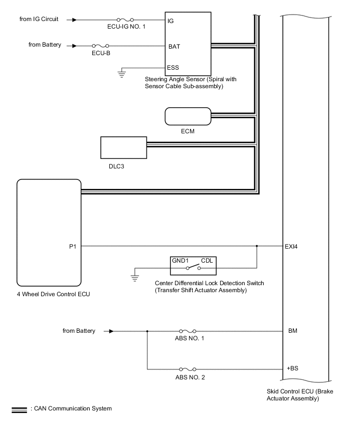
| Skid control ECU (Brake actuator assembly) |
Steering angle sensor (Spiral cable sub-ssembly) |
Steering angle sensor request signal |
CAN communication |
| Steering angle sensor (Spiral cable sub-ssembly) |
Skid control ECU (Brake actuator assembly) |
Steering angle sensor signal |
CAN communication |
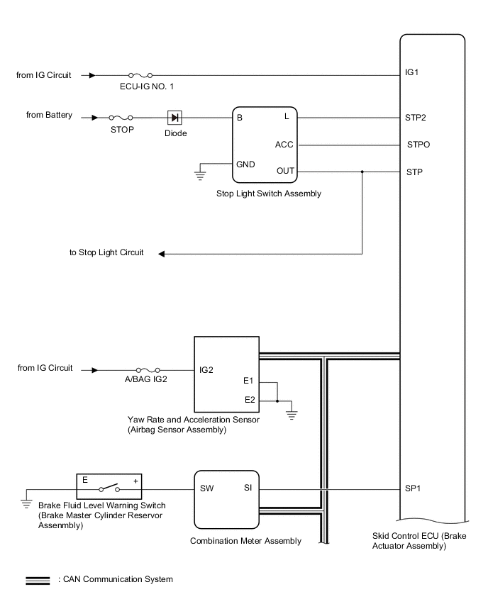
| Skid control ECU (Brake actuator assembly) |
Yaw rate and acceleration sensor (airbag sensor assembly) |
Yaw rate and acceleration request signal |
CAN communication |
| Yaw rate and acceleration sensor (airbag sensor assembly) |
Skid control ECU (Brake actuator assembly) |
Yaw rate and acceleration signal |
CAN communication |
| Skid control ECU (Brake actuator assembly) |
ECM |
|
CAN communication |
| ECM |
Skid control ECU (Brake actuator assembly) |
|
CAN communication |
| Skid control ECU (Brake actuator assembly) |
Combination meter assembly |
Warning/indicator light signal |
CAN communication |
| 4 wheel drive control ECU |
Skid control ECU (Brake actuator assembly) |
|
CAN communication |