VEHICLE STABILITY CONTROL SYSTEM(for Hydraulic Brake Booster) VSC Buzzer Circuit
DESCRIPTION
The skid control ECU (master cylinder solenoid) is connected to the combination meter assembly via CAN communication.
The combination meter assembly has a built-in buzzer.
WIRING DIAGRAM
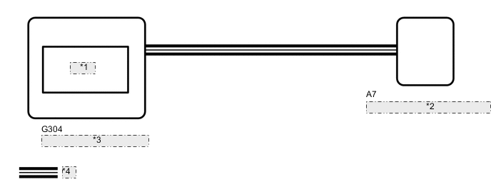
| *1 | Buzzer |
| *2 | Skid Control ECU (Brake Actuator Assembly) |
| *3 | Combination Meter Assembly |
| *4 | CAN Communication Line |
CAUTION / NOTICE / HINT
Note
When replacing the skid control ECU (master cylinder solenoid), perform calibration Click here.
PROCEDURE
-
CHECK CAN COMMUNICATION LINE
-
Turn the ignition switch off.
-
Connect the GTS to the DLC3.
-
Turn the ignition switch to ON.
-
Turn the GTS on.
-
Select CAN Bus Check from the System Selection Menu screen and follow the prompts on the screen to inspect the CAN bus (w/ Central Gateway ECU: See page , w/o Central Gateway ECU: Click here.
OK CAN Bus Check indicates no malfunctions in CAN communication. Result Result Proceed to OK A NG (w/ Central Gateway ECU) B NG (w/o Central Gateway ECU) C
B 
GO TO CAN COMMUNICATION SYSTEM (HOW TO PROCEED WITH TROUBLESHOOTING) Click here
C
GO TO CAN COMMUNICATION SYSTEM (HOW TO PROCEED WITH TROUBLESHOOTING) Click here
A 
-
-
PERFORM ACTIVE TEST USING GTS (BUZZER)
-
Turn the ignition switch off.
-
Connect the GTS to the DLC3.
-
Turn the ignition switch to ON.
-
Turn the GTS on.
-
Enter the following menus: Chassis / ABS/VSC/TRC / Active Test.
ABS/VSC/TRC Tester Display Test Part Control Range Diagnostic Note Buzzer Buzzer Buzzer ON/OFF The buzzer can be heard. -
When performing the Buzzer Active Test, check Buzzer in the Data List Click here.
ABS/VSC/TRC Tester Display Measurement Item/Range Normal Condition Diagnostic Note Buzzer Buzzer/ ON or OFF ON: Buzzer on
OFF: Buzzer off
The combination meter has a built-in buzzer. Result Result Proceed to Data List Display Data List Display when Performing Active Test ON/OFF Operation ON Changes between ON and OFF A Does not change between ON and OFF B OFF Changes between ON and OFF A Does not change between ON and OFF B
A
GO TO METER / GAUGE SYSTEM (HOW TO PROCEED WITH TROUBLESHOOTING) Click here
B
-
-
INSPECT COMBINATION METER ASSEMBLY
-
Inspect the combination meter assembly Click here.
Result Result Proceed to NG A OK (for LHD) B OK (for RHD) C
A
REPLACE COMBINATION METER ASSEMBLY Click here
B
REPLACE MASTER CYLINDER SOLENOID Click here
C
REPLACE MASTER CYLINDER SOLENOID Click here
-