VEHICLE STABILITY CONTROL SYSTEM(for Hydraulic Brake Booster) Crawl Indicator Light Remains ON
DESCRIPTION
When crawl control starts after operating the crawl on/off switch, the crawl indicator light turns on.
WIRING DIAGRAM
Refer to Crawl Indicator Light does not Come ON Click here.
CAUTION / NOTICE / HINT
Note
When replacing the skid control ECU (master cylinder solenoid), perform calibration Click here.
PROCEDURE
-
READ VALUE USING GTS (CRAWL CONTROL MAIN SWITCH AND DIAL SWITCH SIGNAL)
-
Turn the ignition switch off.
-
Connect the GTS to the DLC3.
-
Turn the ignition switch to ON.
-
Turn the GTS on.
-
Enter the following menus: Body Electrical / D-SEAT SW / Data List.
-
Check the Data List for proper functioning of the crawl on/off switch (center cluster module switch) and crawl speed selector (center cluster module switch).
D-SEAT SW Tester Display Measurement Item/Range Normal Condition Diagnostic Note Crawl Control Main Switch Crawl on/off switch/ ON or OFF ON: Switch on
OFF: Switch off
- Dial Switch Signal 1 Crawl speed selector/Multi-terrain select road mode selector signal 1/ ON or OFF Switches between ON and OFF according to the ON/OFF Combination Chart below. - Dial Switch Signal 2 Crawl speed selector/Multi-terrain select road mode selector signal 2/ ON or OFF - Dial Switch Signal 3 Crawl speed selector/Multi-terrain select road mode selector signal 3/ ON or OFF -
-
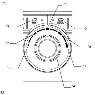
Text in Illustration *1 Center Cluster Module Switch *2 Crawl On/Off Switch *3 Multi-terrain Select Switch *4 Crawl Speed Selector/Multi-terrain Select Road Mode Selector *a Low/MUD & SAND *b Medium-low/LOOSE ROCK *c Medium/MOGUL *d Medium-high/ROCK & DIRT *e High/ROCK Operate the crawl speed selector/multi-terrain select road mode selector and check that "Dial Switch Signal 1", "Dial Switch Signal 2" and "Dial Switch Signal 3" in the Data List display ON and OFF according to the chart shown below.
ON/OFF Combination Chart for "Dial Switch Signal 1", "Dial Switch Signal 2" and "Dial Switch Signal 3" Crawl Speed Selector Position/Multi-terrain Select Road Mode Selector Position Low/MUD & SAND Medium-low/LOOSE ROCK Medium/MOGUL Medium-high/ROCK & DIRT High/ROCK Data List Display Dial Switch Signal 1 ON ON OFF OFF OFF Dial Switch Signal 2 ON OFF OFF OFF ON Dial Switch Signal 3 OFF OFF OFF ON ON OK The GTS display changes according to crawl on/off switch (center cluster module switch) and crawl speed selector (center cluster module switch) operation.
-
NG 
CHECK HARNESS AND CONNECTOR (CENTER CLUSTER MODULE SWITCH - DRIVING SUPPORT SWITCH CONTROL ECU) Click here
OK 
-
-
PERFORM ACTIVE TEST USING GTS (CRAWL CONTROL LIGHT)
-
Turn the ignition switch off.
-
Connect the GTS to the DLC3.
-
Turn the ignition switch to ON.
-
Turn the GTS on.
-
Enter the following menus: Chassis / ABS/VSC/TRC / Active Test.
ABS/VSC/TRC Tester Display Test Part Control Range Diagnostic Note Crawl Control Light Crawl indicator light Indicator light ON/OFF Observe combination meter -
When performing the Crawl Control Light Active Test, check Crawl Control Light in the Data List Click here.
ABS/VSC/TRC Tester Display Measurement Item/Range Normal Condition Diagnostic Note Crawl Control Light Crawl indicator light/ ON or OFF ON: Indicator light on
OFF: Indicator light off
- Result Result Proceed to Data List Display Data List Display when Performing Active Test ON/OFF Operation ON Changes between ON and OFF A Does not change between ON and OFF (for LHD) B Does not change between ON and OFF (for RHD) C OFF Changes between ON and OFF A Does not change between ON and OFF (for LHD) B Does not change between ON and OFF (for RHD) C
A 
GO TO METER / GAUGE SYSTEM (HOW TO PROCEED WITH TROUBLESHOOTING) Click here
B
REPLACE MASTER CYLINDER SOLENOID Click here
C
REPLACE MASTER CYLINDER SOLENOID Click here
-
-
CHECK HARNESS AND CONNECTOR (CENTER CLUSTER MODULE SWITCH - DRIVING SUPPORT SWITCH CONTROL ECU)
-
Disconnect the G156 center cluster module switch connector.
-
Disconnect the G162 driving support switch control ECU connector.
-
Measure the resistance according to the value(s) in the table below.
Standard Resistance Tester Connection Condition Specified Condition G162-6 (CRWL) - G156-21 (FRB) Always Below 1 Ω G162-4 (MOD1) - G156-17 (ECU) Always Below 1 Ω G162-11 (MOD3) - G156-19 (DN) Always Below 1 Ω G162-2 (MOD2) - G156-18 (UP) Always Below 1 Ω G156-24 (E) - Body ground Always Below 1 Ω G162-6 (CRWL) or G156-21 (FRB) - Body ground Always 10 kΩ or higher G162-4 (MOD1) or G156-17 (ECU) - Body ground Always 10 kΩ or higher G162-11 (MOD3) or G156-19 (DN) - Body ground Always 10 kΩ or higher G162-2 (MOD2) or G156-18 (UP) - Body ground Always 10 kΩ or higher
NG
REPAIR OR REPLACE HARNESS OR CONNECTOR
OK
-
-
INSPECT CENTER CLUSTER MODULE SWITCH
-
Remove the center cluster module switch Click here.
-
Inspect the crawl on/off switch (center cluster module switch) and crawl speed selector (center cluster module switch) Click here.
OK
REPLACE DRIVING SUPPORT SWITCH CONTROL ECU Click here
NG
REPLACE CENTER CLUSTER MODULE SWITCH Click here
-