VEHICLE STABILITY CONTROL SYSTEM(for Hydraulic Brake Booster), Diagnostic DTC:C1380

| DTC Code | DTC Name |
|---|---|
| C1380 | Stop Light Control Relay Malfunction |
DESCRIPTION
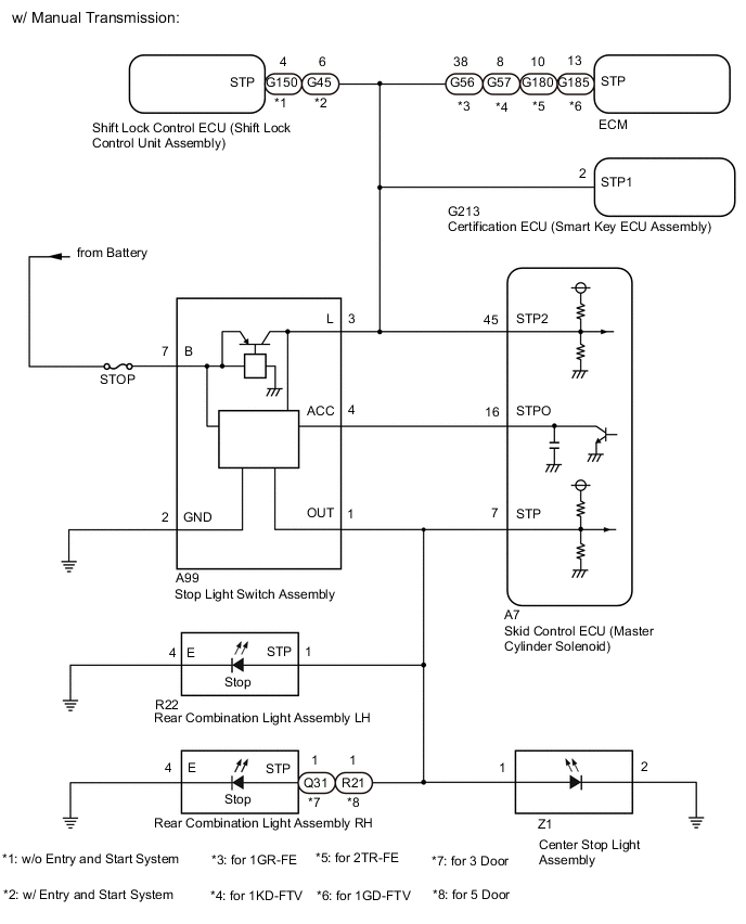
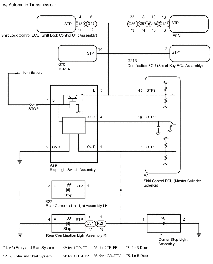
When the skid control ECU (master cylinder solenoid) applies the brakes after receiving a brake request signal from the pre-collision system, dynamic radar cruise control system, secondary collision brake system or brake hold control system, the skid control ECU (master cylinder solenoid) operates the stop light control relay (stop light switch assembly) to illuminate the stop lights.
| DTC No. | Detection Item | DTC Detection Condition | Trouble Area |
|---|---|---|---|
| C1380 | Stop Light Control Relay Malfunction | Either condition is met:
|
|
Tech Tips
DTC will be output when conditions for either of the patterns in the table above are met.
WIRING DIAGRAM
CAUTION / NOTICE / HINT
Note
-
When replacing the skid control ECU (master cylinder solenoid), perform system variant learning and acceleration sensor zero point calibration Click here.
-
Inspect the fuses for circuits related to this system before performing the following procedure.
PROCEDURE
-
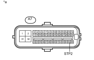
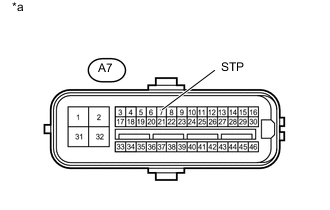
CHECK HARNESS AND CONNECTOR (STP2, STPO AND STP TERMINAL)
-
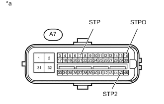
*a Front view of wire harness connector
(to Skid Control ECU (Master Cylinder Solenoid))
Turn the engine switch off.
-
Make sure that there is no looseness at the locking part and the connecting part of the connector.
OK The connector is securely connected. -
Disconnect the A7 skid control ECU (master cylinder solenoid) connector.
-
Check both the connector case and the terminals for deformation and corrosion.
OK No deformation or corrosion. -
Measure the voltage according to the value(s) in the table below.
Standard Voltage Tester Connection Condition Specified Condition A7-7 (STP) - Body ground Stop light switch assembly on (Brake pedal depressed) 11 to 14 V* A7-7 (STP) - Body ground Stop light switch assembly off (Brake pedal released) Below 1.5 V A7-16 (STPO) - Body ground Always 11 to 14 V A7-45 (STP2) - Body ground Stop light switch assembly on (Brake pedal depressed) 11 to 14 V* A7-45 (STP2) - Body ground Stop light switch assembly off (Brake pedal released) Below 1.5 V Tech Tips
*: The minimum voltage value varies depending on the +BS terminal voltage value. The minimum voltage is 85% or more of the +BS terminal voltage.
Result Result Proceed to All terminal voltages are normal A Only STP2 terminal voltage abnormal B Only STPO terminal voltage abnormal C Only STP terminal voltage abnormal D STPO terminal and STP terminal voltage abnormal E
B 
CHECK HARNESS AND CONNECTOR (MASTER CYLINDER SOLENOID - SMART KEY ECU ASSEMBLY) Click here
C
CHECK HARNESS AND CONNECTOR (MASTER CYLINDER SOLENOID - STOP LIGHT SWITCH ASSEMBLY) Click here
D
CHECK HARNESS AND CONNECTOR (MASTER CYLINDER SOLENOID - REAR COMBINATION LIGHT ASSEMBLY LH) Click here
E
CHECK STOP LIGHT SWITCH ASSEMBLY POWER SOURCE CIRCUIT Click here
A 
-
-
PERFORM ACTIVE TEST USING GTS (STOP LIGHT RELAY)
-
Reconnect the A7 skid control ECU (master cylinder solenoid) connector.
-
Enter the following menus: Chassis / ABS/VSC/TRC / Active Test.
Chassis > ABS/VSC/TRC > Active Test Tester Display Measurement Item Control Range Diagnostic Note Stop Light Relay Stop light control relay (Stop light switch assembly) Relay OFF/ON Stop lights come on OK Stop light turns ON/OFF in response to the GTS operation Result Proceed to OK NG
NG
INSPECT MASTER CYLINDER SOLENOID Click here
OK
-
-
CHECK FOR DTC
-
Clear the DTCs Click here.
-
Enter the following menus: Chassis / ABS/VSC/TRC / Active Test.
Chassis > ABS/VSC/TRC > Active Test Tester Display Measurement Item Control Range Diagnostic Note Stop Light Relay Stop light control relay (Stop light switch assembly) Relay OFF/ON Stop lights come on -
According to the display on the GTS, perform the Active Test.
-
Check if the same DTC is output Click here.
Result Result Proceed to C1380 is output A C1380 is not output B
A 
REPLACE MASTER CYLINDER SOLENOID (for LHD: Click here
REPLACE MASTER CYLINDER SOLENOID (for RHD: Click hereB
USE SIMULATION METHOD TO CHECK Click here
-
-
INSPECT MASTER CYLINDER SOLENOID
-
Enter the following menus: Chassis / ABS/VSC/TRC / Active Test.
Chassis > ABS/VSC/TRC > Active Test Tester Display Measurement Item Control Range Diagnostic Note Stop Light Relay Stop light control relay (Stop light switch assembly) Relay OFF/ON Stop lights come on -
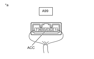
*a Component with harness connected
(Stop Light Switch Assembly)
Measure the voltage according to the value(s) in the table below.
Standard Voltage Tester Connection Condition Specified Condition A99-4 (ACC) - Body ground Active Test is on Below 1.5 V Result Proceed to OK NG
OK
REPLACE STOP LIGHT SWITCH ASSEMBLY Click here
NG
REPLACE MASTER CYLINDER SOLENOID (for LHD: Click here
REPLACE MASTER CYLINDER SOLENOID (for RHD: Click here -
-
CHECK HARNESS AND CONNECTOR (MASTER CYLINDER SOLENOID - SMART KEY ECU ASSEMBLY)
-
*a Front view of wire harness connector
(to Skid Control ECU (Master Cylinder Solenoid))
Make sure that there is no looseness at the locking part and the connecting part of the connector.
OK The connector is securely connected. -
Disconnect the G213 certification ECU (smart key ECU assembly) connector.
-
Check both the connector case and the terminals for deformation and corrosion.
OK No deformation or corrosion. -
Measure the voltage according to the value(s) in the table below.
Standard Voltage Tester Connection Condition Specified Condition A7-45 (STP2) - Body ground Stop light switch assembly on (Brake pedal depressed) 11 to 14 V* A7-45 (STP2) - Body ground Stop light switch assembly off (Brake pedal released) Below 1.5 V Tech Tips
*: The minimum voltage value varies depending on the +BS terminal voltage value. The minimum voltage is 85% or more of the +BS terminal voltage.
Result Result Proceed to OK A NG B
A
REPLACE SMART KEY ECU ASSEMBLY
B
-
-
CHECK HARNESS AND CONNECTOR (MASTER CYLINDER SOLENOID - ECM)
-
*a Front view of wire harness connector
(to Skid Control ECU (Master Cylinder Solenoid))
Make sure that there is no looseness at the locking part and the connecting part of the connector.
OK The connector is securely connected. -
Disconnect the G56*1, G57*2 or G185*4 ECM connector.
-
*1: for 1GR-FE
-
*2: for 1KD-FTV
-
*4: for 1GD-FTV
-
-
Check both the connector case and the terminals for deformation and corrosion.
OK No deformation or corrosion. -
Measure the voltage according to the value(s) in the table below.
Standard Voltage Tester Connection Condition Specified Condition A7-45 (STP2) - Body ground Stop light switch assembly on (Brake pedal depressed) 11 to 14 V* A7-45 (STP2) - Body ground Stop light switch assembly off (Brake pedal released) Below 1.5 V Tech Tips
*: The minimum voltage value varies depending on the +BS terminal voltage value. The minimum voltage is 85% or more of the +BS terminal voltage.
Result Proceed to OK NG
OK
REPLACE ECM (for 1GR-FE: Click here
REPLACE ECM (for 1KD-FTV: Click here
REPLACE ECM (for 2TR-FE: Click here
REPLACE ECM (for 1GD-FTV: Click hereNG
-
-
CHECK HARNESS AND CONNECTOR (MASTER CYLINDER SOLENOID - SHIFT LOCK CONTROL UNIT ASSEMBLY)
-
*a Front view of wire harness connector
(to Skid Control ECU (Master Cylinder Solenoid))
Make sure that there is no looseness at the locking part and the connecting part of the connector.
OK The connector is securely connected. -
Disconnect the G150*1 or G45*2 shift lock control ECU (shift lock control unit assembly) connector.
-
*1: w/o Entry and Start System
-
*2: w/ Entry and Start System
-
-
Check both the connector case and the terminals for deformation and corrosion.
OK No deformation or corrosion. -
Measure the voltage according to the value(s) in the table below.
Standard Voltage Tester Connection Condition Specified Condition A7-45 (STP2) - Body ground Stop light switch assembly on (Brake pedal depressed) 11 to 14 V* A7-45 (STP2) - Body ground Stop light switch assembly off (Brake pedal released) Below 1.5 V Tech Tips
*: The minimum voltage value varies depending on the +BS terminal voltage value. The minimum voltage is 85% or more of the +BS terminal voltage.
Result Proceed to OK NG (for 1KD-FTV (for Automatic Transmission)) NG (except 1KD-FTV (for Automatic Transmission))
OK
REPLACE SHIFT LOCK CONTROL UNIT ASSEMBLY (for A750F: Click here
REPLACE SHIFT LOCK CONTROL UNIT ASSEMBLY (for AC60F: Click hereNG (except 1KD-FTV (for Automatic Transmission))
GO TO STEP 9 Click here
NG (for 1KD-FTV (for Automatic Transmission))
-
-
CHECK HARNESS AND CONNECTOR (MASTER CYLINDER SOLENOID - TCM)
-
*a Front view of wire harness connector
(to Skid Control ECU (Master Cylinder Solenoid))
Make sure that there is no looseness at the locking part and the connecting part of the connector.
OK The connector is securely connected. -
Disconnect the G70 TCM connector.
-
Check both the connector case and the terminals for deformation and corrosion.
OK No deformation or corrosion. -
Measure the voltage according to the value(s) in the table below.
Standard Voltage Tester Connection Condition Specified Condition A7-45 (STP2) - Body ground Stop light switch assembly on (Brake pedal depressed) 11 to 14 V* A7-45 (STP2) - Body ground Stop light switch assembly off (Brake pedal released) Below 1.5 V Tech Tips
*: The minimum voltage value varies depending on the +BS terminal voltage value. The minimum voltage is 85% or more of the +BS terminal voltage.
Result Proceed to OK NG
OK
REPLACE TMC Click here
NG
-
-
CHECK HARNESS AND CONNECTOR (MASTER CYLINDER SOLENOID - STOP LIGHT SWITCH ASSEMBLY)
-
*a Front view of wire harness connector
(to Skid Control ECU (Master Cylinder Solenoid))
Make sure that there is no looseness at the locking part and the connecting part of the connector.
OK The connector is securely connected. -
Disconnect the A99 stop light switch assembly connector.
-
Check both the connector case and the terminals for deformation and corrosion.
OK No deformation or corrosion. -
Measure the voltage according to the value(s) in the table below.
Standard Voltage Tester Connection Condition Specified Condition A7-45 (STP2) - Body ground Always Below 1.5 V Result Proceed to OK NG
NG
REPAIR OR REPLACE HARNESS OR CONNECTOR
OK
-
-
CHECK HARNESS AND CONNECTOR (MASTER CYLINDER SOLENOID - STOP LIGHT SWITCH ASSEMBLY)
-
Measure the resistance according to the value(s) in the table below.
Standard Resistance Tester Connection Condition Specified Condition A7-45 (STP2) - A99-3 (L) Always Below 1 Ω A7-45 (STP2) or A99-3 (L) - Body ground Always 10 kΩ or higher Result Proceed to OK NG
OK
REPLACE STOP LIGHT SWITCH ASSEMBLY Click here
NG
REPAIR OR REPLACE HARNESS OR CONNECTOR
-
-
CHECK HARNESS AND CONNECTOR (MASTER CYLINDER SOLENOID - STOP LIGHT SWITCH ASSEMBLY)
-
Make sure that there is no looseness at the locking part and the connecting part of the connector.
OK The connector is securely connected. -
Disconnect the A99 stop light switch assembly connector.
-
Check both the connector case and the terminals for deformation and corrosion.
OK No deformation or corrosion. -
Measure the resistance according to the value(s) in the table below.
Standard Resistance Tester Connection Condition Specified Condition A7-16 (STPO) - A99-4 (ACC) Always Below 1 Ω Result Proceed to OK NG
OK
REPLACE STOP LIGHT SWITCH ASSEMBLY Click here
NG
REPAIR OR REPLACE HARNESS OR CONNECTOR
-
-
CHECK HARNESS AND CONNECTOR (MASTER CYLINDER SOLENOID - REAR COMBINATION LIGHT ASSEMBLY LH)
-
*a Front view of wire harness connector
(to Skid Control ECU (Master Cylinder Solenoid))
Make sure that there is no looseness at the locking part and the connecting part of the connector.
OK The connector is securely connected. -
Disconnect the R22 rear combination light assembly LH connector.
-
Check both the connector case and the terminals for deformation and corrosion.
OK No deformation or corrosion. -
Measure the voltage according to the value(s) in the table below.
Standard Voltage Tester Connection Condition Specified Condition A7-7 (STP) - Body ground Stop light switch assembly on (Brake pedal depressed) 11 to 14 V* A7-7 (STP) - Body ground Stop light switch assembly off (Brake pedal released) Below 1.5 V Tech Tips
*: The minimum voltage value varies depending on the +BS terminal voltage value. The minimum voltage is 85% or more of the +BS terminal voltage.
Result Proceed to OK NG
OK
REPLACE REAR COMBINATION LIGHT ASSEMBLY LH Click here
NG
-
-
CHECK HARNESS AND CONNECTOR (MASTER CYLINDER SOLENOID - REAR COMBINATION LIGHT ASSEMBLY RH)
-
*a Front view of wire harness connector
(to Skid Control ECU (Master Cylinder Solenoid))
Make sure that there is no looseness at the locking part and the connecting part of the connector.
OK The connector is securely connected. -
Disconnect the Q31*1 or R21*2 rear combination light assembly RH connector.
-
*1: for 3 Door
-
*2: for 5 Door
-
-
Check both the connector case and the terminals for deformation and corrosion.
OK No deformation or corrosion. -
Measure the voltage according to the value(s) in the table below.
Standard Voltage Tester Connection Condition Specified Condition A7-7 (STP) - Body ground Stop light switch assembly on (Brake pedal depressed) 11 to 14 V* A7-7 (STP) - Body ground Stop light switch assembly off (Brake pedal released) Below 1.5 V Tech Tips
*: The minimum voltage value varies depending on the +BS terminal voltage value. The minimum voltage is 85% or more of the +BS terminal voltage.
Result Proceed to OK NG
OK
REPLACE REAR COMBINATION LIGHT ASSEMBLY RH Click here
NG
-
-
CHECK HARNESS AND CONNECTOR (MASTER CYLINDER SOLENOID - CENTER STOP LIGHT ASSEMBLY)
-
*a Front view of wire harness connector
(to Skid Control ECU (Master Cylinder Solenoid))
Make sure that there is no looseness at the locking part and the connecting part of the connector.
OK The connector is securely connected. -
Disconnect the Z1 center stop light assembly connector.
-
Check both the connector case and the terminals for deformation and corrosion.
OK No deformation or corrosion. -
Measure the voltage according to the value(s) in the table below.
Standard Voltage Tester Connection Condition Specified Condition A7-7 (STP) - Body ground Stop light switch assembly on (Brake pedal depressed) 11 to 14 V* A7-7 (STP) - Body ground Stop light switch assembly off (Brake pedal released) Below 1.5 V Tech Tips
*: The minimum voltage value varies depending on the +BS terminal voltage value. The minimum voltage is 85% or more of the +BS terminal voltage.
Result Proceed to OK NG
OK
REPLACE CENTER STOP LIGHT ASSEMBLY Click here
NG
-
-
CHECK HARNESS AND CONNECTOR (MASTER CYLINDER SOLENOID - STOP LIGHT SWITCH ASSEMBLY)
-
*a Front view of wire harness connector
(to Skid Control ECU (Master Cylinder Solenoid))
Make sure that there is no looseness at the locking part and the connecting part of the connector.
OK The connector is securely connected. -
Disconnect the A99 stop light switch assembly connector.
-
Check both the connector case and the terminals for deformation and corrosion.
OK No deformation or corrosion. -
Measure the voltage according to the value(s) in the table below.
Standard Voltage Tester Connection Condition Specified Condition A7-7 (STP) - Body ground Always Below 1.5 V Result Proceed to OK NG
NG
REPAIR OR REPLACE HARNESS OR CONNECTOR
OK
-
-
CHECK HARNESS AND CONNECTOR (MASTER CYLINDER SOLENOID - STOP LIGHT SWITCH ASSEMBLY)
-
Measure the resistance according to the value(s) in the table below.
Standard Resistance Tester Connection Condition Specified Condition A99-1 (OUT) - A7-7 (STP) Always Below 1 Ω A99-1 (OUT) or A7-7 (STP) - Body ground Always 10 kΩ or higher Result Proceed to OK NG
OK
REPLACE STOP LIGHT SWITCH ASSEMBLY Click here
NG
REPAIR OR REPLACE HARNESS OR CONNECTOR
-
-
CHECK STOP LIGHT SWITCH ASSEMBLY POWER SOURCE CIRCUIT
-
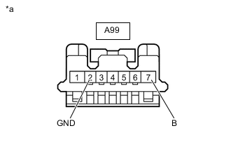
*a Front view of wire harness connector
(to Stop Light Switch Assembly)
Make sure that there is no looseness at the locking part and the connecting part of the connector.
OK The connector is securely connected. -
Disconnect the A99 stop light switch assembly connector.
-
Check both the connector case and the terminals for deformation and corrosion.
OK No deformation or corrosion. -
Measure the resistance according to the value(s) in the table below.
Standard Resistance Tester Connection Condition Specified Condition A99-2 (GND) - Body ground Always Below 1 Ω -
Measure the voltage according to the value(s) in the table below.
Standard Voltage Tester Connection Condition Specified Condition A99-7 (B) - Body ground Always 11 to 14 V Result Proceed to OK NG
NG
REPAIR OR REPLACE HARNESS OR CONNECTOR
OK
-
-
CHECK HARNESS AND CONNECTOR (MASTER CYLINDER SOLENOID - STOP LIGHT SWITCH ASSEMBLY)
-
Measure the resistance according to the value(s) in the table below.
Standard Resistance Tester Connection Condition Specified Condition A7-16 (STPO) or A99-4 (ACC) - Body ground Always 10 kΩ or higher Result Proceed to OK NG
OK
REPLACE STOP LIGHT SWITCH ASSEMBLY Click here
NG
REPAIR OR REPLACE HARNESS OR CONNECTOR
-