VEHICLE STABILITY CONTROL SYSTEM(for Hydraulic Brake Booster), Diagnostic DTC:C1379

| DTC Code | DTC Name |
|---|---|
| C1379 | Downhill Assist Control Switch Malfunction (Test Mode DTC) |
DESCRIPTION
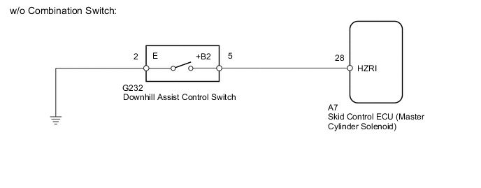
w/o Combination Switch (w/ Downhill Assist Control):
DTC C1379 is cleared when the downhill assist control switch sends a downhill assist control operation signal or when test mode ends.
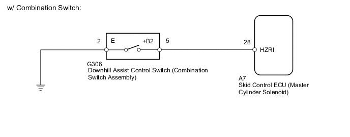
w/ Combination Switch:
DTC C1379 is cleared when the crawl on/off switch (combination switch assembly) and crawl speed selector (combination switch assembly) send a crawl control operation signal or when test mode ends.
| DTC Code | DTC Detection Condition | Trouble Area |
|---|---|---|
| C1379 | Stored only during test mode. |
|
WIRING DIAGRAM
CAUTION / NOTICE / HINT
Note
When replacing the skid control ECU (master cylinder solenoid), perform calibration Click here.
PROCEDURE
-
READ VALUE USING GTS (DOWNHILL ASSIST CONTROL SW)
-
Turn the ignition switch off.
-
Connect the GTS to the DLC3.
-
Turn the ignition switch to ON.
-
Turn the GTS on.
-
Enter the following menus: Chassis / ABS/VSC/TRC / Data List.
-
Check the Data List for proper functioning of the downhill assist control switch.
ABS/VSC/TRC Tester Display Measurement Item/Range Normal Condition Diagnostic Note Downhill Assist Control SW Downhill assist control switch / ON or OFF ON: Downhill assist control on
OFF: Downhill assist control off
- OK The GTS displays ON or OFF according to downhill assist control switch operation. Result Result Proceed to OK A NG (w/o Crawl Control) B NG (w/ Crawl Control) C
B 
INSPECT DOWNHILL ASSIST CONTROL SWITCH Click here
C
INSPECT COMBINATION SWITCH ASSEMBLY Click here
A 
-
-
CHECK TEST MODE DTC
-
Perform the downhill assist control switch check in the Test Mode Procedure Click here.
OK Test mode DTC C1379 is cleared. Result Result Proceed to OK A NG (for LHD) B NG (for RHD) C
A 
USE SIMULATION METHOD TO CHECK Click here
B
REPLACE MASTER CYLINDER SOLENOID Click here
C
REPLACE MASTER CYLINDER SOLENOID Click here
-
-
INSPECT DOWNHILL ASSIST CONTROL SWITCH
-
Remove the downhill assist control switch Click here.
-
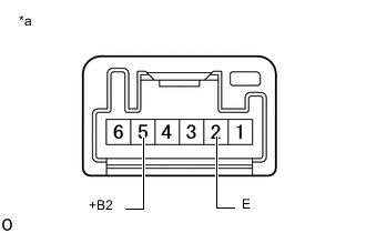
Text in Illustration *a Component without harness connected
(Downhill Assist Control Switch)
Measure the resistance according to the value(s) in the table below.
Standard Resistance Tester Connection Switch Condition Specified Condition 2 - 5 Not pushed in 10 kΩ or higher Pushed in Below 1 Ω
NG
REPLACE DOWNHILL ASSIST CONTROL SWITCH Click here
OK
-
-
CHECK HARNESS AND CONNECTOR (MASTER CYLINDER SOLENOID - DOWNHILL ASSIST CONTROL SWITCH)
-
Disconnect the A7 skid control ECU (master cylinder solenoid) connector.
-
Disconnect the G232 downhill assist control switch connector.
-
Measure the resistance according to the value(s) in the table below.
Standard Resistance Tester Connection Condition Specified Condition A7-28 (HZRI) - G232-5 (+B2) Always Below 1 Ω A7-28 (HZRI) or G232-5 (+B2) - Body ground Always 10 kΩ or higher G232-2 (E) - Body ground Always Below 1 Ω Result Result Proceed to OK (for LHD) A OK (for RHD) B NG C
A
REPLACE MASTER CYLINDER SOLENOID Click here
B
REPLACE MASTER CYLINDER SOLENOID Click here
C
REPAIR OR REPLACE HARNESS OR CONNECTOR
-
-
INSPECT COMBINATION SWITCH ASSEMBLY
-
Remove the combination switch assembly Click here.
-
Inspect the combination switch assembly Click here.
NG
REPLACE COMBINATION SWITCH ASSEMBLY Click here
OK
-
-
CHECK HARNESS AND CONNECTOR (COMBINATION SWITCH ASSEMBLY - MASTER CYLINDER SOLENOID)
-
Disconnect the G156 downhill assist control switch (combination switch assembly) connector.
-
Disconnect the A7 skid control ECU (master cylinder solenoid) connector.
-
Measure the resistance according to the value(s) in the table below.
Standard Resistance Tester Connection Condition Specified Condition A7-28 (HZRI) - G306-5 (+B2) Always Below 1 Ω A7-28 (HZRI) or G306-5 (+B2) - Body ground Always 10 kΩ or higher G306-2 (E) - Body ground Always Below 1 Ω Result Result Proceed to OK (for LHD) A OK (for RHD) B NG C
A
REPLACE MASTER CYLINDER SOLENOID Click here
B
REPLACE MASTER CYLINDER SOLENOID Click here
C
REPAIR OR REPLACE HARNESS OR CONNECTOR
-