VEHICLE STABILITY CONTROL SYSTEM(for Hydraulic Brake Booster) TRC OFF Indicator Light Remains ON
DESCRIPTION
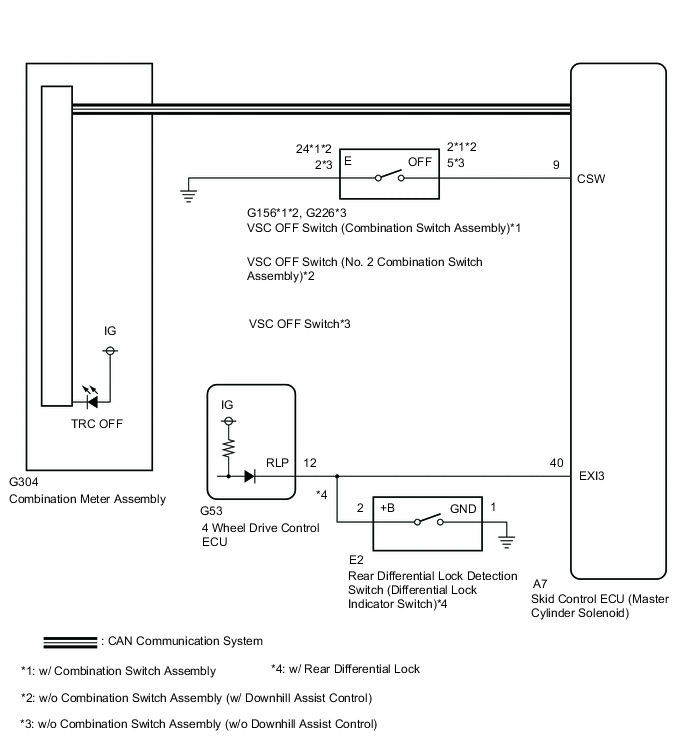
The skid control ECU is connected to the combination meter via the CAN communication system. Pressing the VSC OFF switch turns off traction control and pressing and holding this switch turns off traction control and VSC. If traction control turns off, the TRC OFF indicator light comes on.
When the temperature inside the hydraulic brake booster becomes too high, the TRC OFF indicator light turns on and traction control is stopped until the temperature decreases.
-
When the transfer is in L4, VSC is prohibited and the VSC OFF indicator and TRC OFF indicator lights turn on.
-
w/ Rear Differential Lock:
When the rear differential lock is in the locked state, VSC is prohibited and the VSC OFF indicator and TRC OFF indicator lights turn on. At this time, ABS is also prohibited and the ABS warning light turns on.
WIRING DIAGRAM
CAUTION / NOTICE / HINT
Note
-
When replacing skid control ECU (master cylinder solenoid), perform calibration Click here.
-
As there may be malfunctions in the transfer system related to when the transfer operates in L4, check the transfer system first Click here.
PROCEDURE
-
CHECK CAN COMMUNICATION LINE
-
Turn the ignition switch off.
-
Connect the GTS to the DLC3.
-
Turn the ignition switch to ON.
-
Turn the GTS on.
-
Select CAN Bus Check from the System Selection Menu screen and follow the prompts on the screen to inspect the CAN bus (w/ Central Gateway ECU: See page , w/o Central Gateway ECU: Click here.
OK CAN Bus Check indicates no malfunctions in CAN communication. Result Result Proceed to OK A NG (w/ Central Gateway ECU) B NG (w/o Central Gateway ECU) C
B 
GO TO CAN COMMUNICATION SYSTEM (HOW TO PROCEED WITH TROUBLESHOOTING) Click here
C
GO TO CAN COMMUNICATION SYSTEM (HOW TO PROCEED WITH TROUBLESHOOTING) Click here
A 
-
-
CHECK HARNESS AND CONNECTOR (MASTER CYLINDER SOLENOID CSW CIRCUIT)
-
Disconnect the A7 skid control ECU (master cylinder solenoid) connector.
-
Measure the resistance according to the value(s) in the table below.
Standard Resistance Tester Connection Switch Condition Specified Condition A7-9 (CSW) - Body ground VSC OFF switch not pushed in 10 kΩ or higher VSC OFF switch pushed in Below 1 Ω Result Result Proceed to OK A NG (w/ Combination Switch Assembly) B NG (w/o Combination Switch Assembly (w/ Downhill Assist Control)) C NG (w/o Combination Switch Assembly (w/o Downhill Assist Control)) D
B 
CHECK HARNESS AND CONNECTOR (MASTER CYLINDER SOLENOID - COMBINATION SWITCH ASSEMBLY) Click here
C
CHECK HARNESS AND CONNECTOR (MASTER CYLINDER SOLENOID - NO. 2 COMBINATION SWITCH ASSEMBLY) Click here
D
CHECK HARNESS AND CONNECTOR (MASTER CYLINDER SOLENOID - VSC OFF SWITCH) Click here
A
-
-
CHECK TERMINAL VOLTAGE (EXI3)
-
Disconnect the A7 skid control ECU (master cylinder solenoid) connector.
-
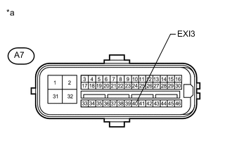
Text in Illustration *a Front view of wire harness connector
(to Skid Control ECU (Master Cylinder Solenoid))
Measure the voltage according to the value(s) in the table below.
Standard Voltage Tester Connection Switch Condition Specified Condition A7-40 (EXI3) - Body ground Ignition switch ON
w/ Rear Differential Lock: Rear differential free
11 to 14 V
NG
CHECK HARNESS AND CONNECTOR (MASTER CYLINDER SOLENOID EXI3 CIRCUIT) Click here
OK
-
-
READ VALUE USING GTS (TRC/VSC OFF MODE)
-
Turn the ignition switch off.
-
Connect the GTS to the DLC3.
-
Turn the ignition switch to ON.
-
Turn the GTS on.
-
Enter the following menus: Chassis / ABS/VSC/TRC / Data List.
ABS/VSC/TRC Tester Display Measurement Item/Range Normal Condition Diagnostic Note TRC/VSC Off Mode TRC/VSC off mode/ Normal, TRC OFF or VSC OFF Normal: Normal mode
TRC OFF: TRC OFF mode
VSC OFF: VSC OFF mode
- -
Check that the mode display changes according to VSC OFF switch operation.
OK Display changes according to switch operation. Result Result Proceed to OK A NG (for LHD) B NG (for RHD) C
A
GO TO METER / GAUGE SYSTEM (HOW TO PROCEED WITH TROUBLESHOOTING) Click here
B
REPLACE MASTER CYLINDER SOLENOID Click here
C
REPLACE MASTER CYLINDER SOLENOID Click here
-
-
CHECK HARNESS AND CONNECTOR (MASTER CYLINDER SOLENOID - COMBINATION SWITCH ASSEMBLY)
-
Disconnect the G156 VSC OFF switch (combination switch assembly) connector.
-
Measure the resistance according to the value(s) in the table below.
Standard Resistance Tester Connection Condition Specified Condition A7-9 (CSW) - G156-2 (OFF) Always Below 1 Ω A7-9 (CSW) - Body ground Always 10 kΩ or higher G156-24 (E) - Body ground Always Below 1 Ω
OK
INSPECT COMBINATION SWITCH ASSEMBLY Click here
NG
REPAIR OR REPLACE HARNESS OR CONNECTOR
-
-
CHECK HARNESS AND CONNECTOR (MASTER CYLINDER SOLENOID - NO. 2 COMBINATION SWITCH ASSEMBLY)
-
Disconnect the G156 VSC OFF switch (No. 2 combination switch assembly) connector.
-
Measure the resistance according to the value(s) in the table below.
Standard Resistance Tester Connection Condition Specified Condition A7-9 (CSW) - G156-2 (OFF) Always Below 1 Ω A7-9 (CSW) - Body ground Always 10 kΩ or higher G156-24 (E) - Body ground Always Below 1 Ω
OK
INSPECT NO. 2 COMBINATION SWITCH ASSEMBLY Click here
NG
REPAIR OR REPLACE HARNESS OR CONNECTOR
-
-
CHECK HARNESS AND CONNECTOR (MASTER CYLINDER SOLENOID - VSC OFF SWITCH)
-
Disconnect the A7 skid control ECU (master cylinder solenoid) connector.
-
Disconnect the G226 VSC OFF switch connector.
-
Measure the resistance according to the value(s) in the table below.
Standard Resistance Tester Connection Condition Specified Condition A7-9 (CSW) - G226-5 (OFF) Always Below 1 Ω A7-9 (CSW) - Body ground Always 10 kΩ or higher G226-2 (E) - Body ground Always Below 1 Ω
OK
INSPECT VSC OFF SWITCH Click here
NG
REPAIR OR REPLACE HARNESS OR CONNECTOR
-
-
INSPECT COMBINATION SWITCH ASSEMBLY
-
Remove the VSC OFF switch (combination switch assembly) Click here.
-
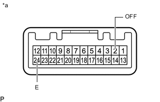
Text in Illustration *a Component without harness connected
(VSC OFF Switch (Combination Switch Assembly))
Measure the resistance according to the value(s) in the table below.
Standard Resistance Tester Connection Switch Condition Specified Condition 2 (OFF) - 24 (E) Switch is not pushed 10 kΩ or higher Switch is pushed Below 1 Ω Result Result Proceed to NG A OK (for LHD) B OK (for RHD) C
A
REPLACE COMBINATION SWITCH ASSEMBLY Click here
B
REPLACE MASTER CYLINDER SOLENOID Click here
C
REPLACE MASTER CYLINDER SOLENOID Click here
-
-
INSPECT NO. 2 COMBINATION SWITCH ASSEMBLY
-
Remove the VSC OFF switch (No. 2 combination switch assembly) Click here.
-
Text in Illustration *a Component without harness connected
(VSC OFF Switch (No. 2 Combination Switch Assembly))
Measure the resistance according to the value(s) in the table below.
Standard Resistance Tester Connection Switch Condition Specified Condition 2 (OFF) - 24 (E) Switch is not pushed 10 kΩ or higher Switch is pushed Below 1 Ω Result Result Proceed to NG A OK (for LHD) B OK (for RHD) C
A
REPLACE NO. 2 COMBINATION SWITCH ASSEMBLY Click here
B
REPLACE MASTER CYLINDER SOLENOID Click here
C
REPLACE MASTER CYLINDER SOLENOID Click here
-
-
INSPECT VSC OFF SWITCH
-
Remove the VSC OFF switch Click here.
-
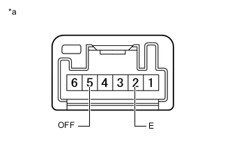
Text in Illustration *a Component without harness connected
(VSC OFF Switch)
Measure the resistance according to the value(s) in the table below.
Standard Resistance Tester Connection Switch Condition Specified Condition 5 (OFF) - 2 (E) Switch is not pushed 10 kΩ or higher Switch is pushed Below 1 Ω Result Result Proceed to NG A OK (for LHD) B OK (for RHD) C
A
REPLACE VSC OFF SWITCH Click here
B
REPLACE MASTER CYLINDER SOLENOID Click here
C
REPLACE MASTER CYLINDER SOLENOID Click here
-
-
CHECK HARNESS AND CONNECTOR (MASTER CYLINDER SOLENOID EXI3 CIRCUIT)
-
Disconnect the A7 skid control ECU connector.
-
Disconnect the G53 4 wheel drive control ECU connector.
-
w/ Rear Differential Lock:
Disconnect the E2 rear differential lock detection switch connector.
-
Measure the resistance according to the value(s) in the table below.
Standard Resistance Tester Connection Condition Specified Condition A7-40 (EXI3) - Body ground Always 10 kΩ or higher Result Result Proceed to OK (w/o Rear Differential Lock) A OK (w/ Rear Differential Lock) B NG C
B
INSPECT REAR DIFFERENTIAL LOCK DETECTION SWITCH (DIFFERENTIAL LOCK INDICATOR SWITCH) Click here
C
REPAIR OR REPLACE HARNESS OR CONNECTOR
A
-
-
CHECK TERMINAL VOLTAGE (EXI3)
-
Disconnect the A7 skid control ECU connector.
-
Connect the G53 4 wheel drive control ECU connector.
-
Text in Illustration *a Front view of wire harness connector
(to Skid Control ECU (Master Cylinder Solenoid))
Measure the voltage according to the value(s) in the table below.
Standard Voltage Tester Connection Switch Condition Specified Condition A7-40 (EXI3) - Body ground Ignition switch ON 11 to 14 V Result Result Proceed to NG A OK (for LHD) B OK (for RHD) C
A
REPLACE 4 WHEEL DRIVE CONTROL ECU Click here
B
REPLACE MASTER CYLINDER SOLENOID Click here
C
REPLACE MASTER CYLINDER SOLENOID Click here
-
-
INSPECT REAR DIFFERENTIAL LOCK DETECTION SWITCH (DIFFERENTIAL LOCK INDICATOR SWITCH)
-
Remove the rear differential lock detection switch Click here.
-
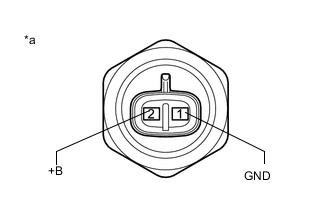
Text in Illustration *a Component without harness connected
(Rear Differential Lock Detection Switch)
Measure the resistance according to the value(s) in the table below.
Standard Resistance Tester Connection Switch Condition Specified Condition 1 (GND) - 2 (+B) Pushed in Below 1 Ω Not pushed in 10 kΩ or higher
NG
REPLACE REAR DIFFERENTIAL LOCK DETECTION SWITCH (DIFFERENTIAL LOCK INDICATOR SWITCH) Click here
OK
-
-
CHECK TERMINAL VOLTAGE (EXI3)
-
Disconnect the A7 skid control ECU connector.
-
Connect the G53 4 wheel drive control ECU connector.
-
Text in Illustration *a Front view of wire harness connector
(to Skid Control ECU (Master Cylinder Solenoid))
Measure the voltage according to the value(s) in the table below.
Standard Voltage Tester Connection Switch Condition Specified Condition A7-40 (EXI3) - Body ground Ignition switch ON 11 to 14 V Result Result Proceed to NG A OK (for LHD) B OK (for RHD) C
A
REPLACE 4 WHEEL DRIVE CONTROL ECU Click here
B
REPLACE MASTER CYLINDER SOLENOID Click here
C
REPLACE MASTER CYLINDER SOLENOID Click here
-