VEHICLE STABILITY CONTROL SYSTEM(for Hydraulic Brake Booster) Multi-terrain Select Indicator Light does not Come ON
DESCRIPTION
When the multi-terrain select switch (center cluster module switch) is operated, multi-terrain select control is enabled and the multi-terrain select indicator light illuminates.
After selecting a road surface type displayed on the multi-information display using the multi-terrain select road mode selector (center cluster module switch), the system optimizes throttle control and brake fluid pressure control for wheels that slip when accelerating, which allows the power lost when wheels slip during acceleration to be distributed to all 4 wheels.
The slip indicator light blinks while the system is operating.
The system can operate under the following conditions:
-
The vehicle stability control system is normal.
-
The system is not in VSC OFF mode or TRC OFF mode.
-
Crawl control is not operating.
-
Shift position not P or N.
-
The transfer is set to L4.
When there is a malfunction in the multi-terrain select system, a message is displayed on the multi-information display.
A mode screen display signal is sent to the combination meter assembly via LIN communication from the driving support switch control ECU to display the multi-terrain select road mode on the multi-information display.
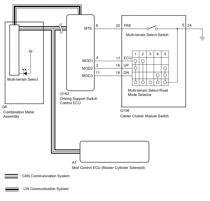
WIRING DIAGRAM
CAUTION / NOTICE / HINT
Note
When replacing the skid control ECU (master cylinder solenoid), perform calibration Click here.
PROCEDURE
-
CHECK CAN COMMUNICATION LINE
-
Turn the ignition switch off.
-
Connect the intelligent tester to the DLC3.
-
Turn the ignition switch to ON.
-
Turn the intelligent tester on.
-
Select CAN Bus Check from the System Selection Menu screen and follow the prompts on the screen to inspect the CAN bus (for LHD: See page , for RHD: Click here.
OK CAN Bus Check indicates no malfunctions in CAN communication. Result Result Proceed to OK A NG (for LHD) B NG (for RHD) C
B 
GO TO CAN COMMUNICATION SYSTEM (HOW TO TROUBLESHOOT ECU CONTROLLED SYSTEMS) Click here
C
GO TO CAN COMMUNICATION SYSTEM (HOW TO TROUBLESHOOT ECU CONTROLLED SYSTEMS) Click here
A 
-
-
CHECK LIN COMMUNICATION LINE
-
Use the GTS to check if the LIN communication system is functioning normally.
Result Result Proceed to LIN DTC is not output A LIN DTC is output B
B
GO TO LIN COMMUNICATION SYSTEM (HOW TO TROUBLESHOOT ECU CONTROLLED SYSTEMS) Click here
A
-
-
CHECK DTC
-
Check for DTCs Click here.
Result Result Proceed to DTC is not output A DTC is output B
B
REPAIR CIRCUITS INDICATED BY OUTPUT DTCS Click here
A
-
-
READ VALUE USING GTS (OFF-ROAD GUIDANCE SWITCH AND DIAL SWITCH SIGNAL)
-
Turn the ignition switch off.
-
Connect the GTS to the DLC3.
-
Turn the ignition switch to ON.
-
Turn the GTS on.
-
Enter the following menus: Body Electrical / D-SEAT SW / Data List.
-
Check the Data List for proper functioning of the multi-terrain select switch (center cluster module switch) and multi-terrain select road mode selector (center cluster module switch).
D-SEAT SW Tester Display Measurement Item/Range Normal Condition Diagnostic Note Off-road Guidance Switch Multi-terrain select switch/ ON or OFF ON: Switch on
OFF: Switch off
- Dial Switch Signal 1 Crawl speed selector/Multi-terrain select road mode selector signal 1/ ON or OFF Switches between ON and OFF according to the ON/OFF Combination Chart Click here
- Dial Switch Signal 2 Crawl speed selector/Multi-terrain select road mode selector signal 2/ ON or OFF - Dial Switch Signal 3 Crawl speed selector/Multi-terrain select road mode selector signal 3/ ON or OFF - OK The GTS display changes according to multi-terrain select switch (center cluster module switch) and multi-terrain select road mode selector (center cluster module switch) operation.
NG 
CHECK HARNESS AND CONNECTOR (CENTER CLUSTER MODULE SWITCH - DRIVING SUPPORT SWITCH CONTROL ECU) Click here
OK
-
-
INSPECT COMBINATION METER ASSEMBLY
-
Perform an Active Test of the combination meter assembly using the GTS Click here.
OK The multi-terrain select indicator light turns on or off in accordance with the Active Test operation. Result Result Proceed to NG A OK (for LHD) B OK (for RHD) C
A
GO TO METER / GAUGE SYSTEM (HOW TO PROCEED WITH TROUBLESHOOTING) Click here
B
REPLACE MASTER CYLINDER SOLENOID Click here
C
REPLACE MASTER CYLINDER SOLENOID Click here
-
-
CHECK HARNESS AND CONNECTOR (CENTER CLUSTER MODULE SWITCH - DRIVING SUPPORT SWITCH CONTROL ECU)
-
Disconnect the G156 center cluster module switch connector.
-
Disconnect the G162 driving support switch control ECU connector.
-
Measure the resistance according to the value(s) in the table below.
Standard Resistance Tester Connection Condition Specified Condition G162-8 (MTS) - G156-20 (FRE) Always Below 1 Ω G162-4 (MOD1) - G156-17 (ECU) Always Below 1 Ω G162-11 (MOD3) - G156-19 (DN) Always Below 1 Ω G162-2 (MOD2) - G156-18 (UP) Always Below 1 Ω G156-24 (E) - Body ground Always Below 1 Ω G162-8 (MTS) or G156-20 (FRE) - Body ground Always 10 kΩ or higher G162-4 (MOD1) or G156-17 (ECU) - Body ground Always 10 kΩ or higher G162-11 (MOD3) or G156-19 (DN) - Body ground Always 10 kΩ or higher G162-2 (MOD2) or G156-18 (UP) - Body ground Always 10 kΩ or higher
NG
REPAIR OR REPLACE HARNESS OR CONNECTOR
OK
-
-
INSPECT CENTER CLUSTER MODULE SWITCH
-
Remove the center cluster module switch Click here.
-
Inspect the multi-terrain select switch (center cluster module switch) and multi-terrain select road mode selector (center cluster module switch) Click here.
OK
REPLACE DRIVING SUPPORT SWITCH CONTROL ECU Click here
NG
REPLACE CENTER CLUSTER MODULE SWITCH Click here
-