VEHICLE STABILITY CONTROL SYSTEM(for Hydraulic Brake Booster) TERMINALS OF ECU

-
TERMINALS OF ECU
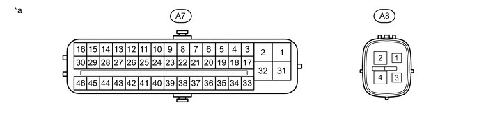
Text in Illustration *a Component without harness connected
(Skid Control ECU)
- - Terminal No. (Symbol) Terminal Description A7-1 (GND1) Skid control ECU ground A7-2 (+BM1) Power supply for motor A7-3 (FR+) Front speed sensor RH power supply output A7-4 (FL-) Front speed sensor LH input A7-5 (RR+) Rear speed sensor RH power supply output A7-6 (RL-) Rear speed sensor LH input A7-7 (STP) Stop light switch A7-9 (CSW) VSC OFF switch A7-11 (CANH) CAN communication terminal high A7-12 (SP1) Speedometer signal A7-16 (STPO) Stop light operation relay A7-17 (FR-) Front speed sensor RH input A7-18 (FL+) Front speed sensor LH power supply output A7-19 (RR-) Rear speed sensor RH input A7-20 (RL+) Rear speed sensor LH power supply output A7-24 (TS) Sensor test terminal (Signal check switch) A7-25 (CANL) CAN communication terminal low A7-27 (EXI) Center differential lock detection switch A7-28 (HZRI) Hazard warning switch A7-30 (BZ)*1 Skid control buzzer A7-31 (+BS) Power supply for solenoid A7-32 (GND2) Skid control ECU ground A7-40 (EXI3) w/ Rear Differential Lock: Rear differential lock detection switch
w/o Rear Differential Lock: Four wheel drive control ECU
A7-41 (LBL) Brake fluid level warning switch A7-42 (EXO) Stop light control relay (Emergency brake signal output) A7-44 (HDCS)*2 Downhill assist control switch A7-45 (STP2) Stop light switch A7-46 (IG1) IG1 power supply A8-1 (IG2) IG2 power supply A8-2 (+BM2) Power supply for motor A8-4 (GND3) Skid control ECU ground
-
*1: w/ Dynamic Radar Cruise Control System
-
*2: w/ Downhill Assist Control
-
-
TERMINAL INSPECTION
Disconnect the 2 skid control ECU connectors and measure the voltage or resistance on the wire harness side.
Tech Tips
Voltage cannot be measured with the connector connected to the skid control ECU as the connector is watertight.
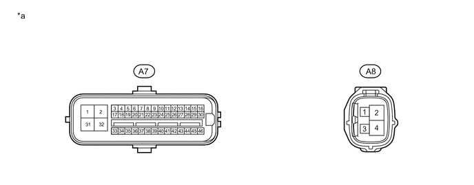
Text in Illustration *a Front view of wire harness connector
(to Skid Control ECU)
- - Terminal No. (Symbol) Wiring Color Terminal Description Condition Specified Condition A7-2 (+BM1) - Body ground B Power supply for motor
(from battery)
Always 11 to 14 V A7-7 (STP) - Body ground V Stop light switch Brake pedal depressed → released 8 to 14 V → Below 1.5 V A7-9 (CSW) - Body ground B VSC OFF switch input VSC OFF switch off → on and held 10 kΩ or higher → Below 1 Ω A7-16 (STPO) - Body ground LG Stop light operation relay Ignition switch off → ON Below 1.1 V → 11 to 14 V A7-31 (+BS) - Body ground L-R Power supply for solenoid
(from battery)
Always 11 to 14 V A7-41 (LBL) - Body ground V-G Brake fluid level warning switch Brake fluid level +/-5 mm (+/-0.196 in.) from minimum level → maximum level Below 1 Ω → 1.9 to 2.1 kΩ A7-44 (HDCS)* - Body ground W-L Downhill assist control switch input Downhill assist control switch off → on 10 kΩ or higher → Below 1 Ω A7-45 (STP2) - Body ground L Stop light switch Brake pedal depressed → released 8 to 14 V → Below 1.5 V A7-46 (IG1) - Body ground G IG1 power supply Ignition switch off → ON Below 1 V → 11 to 14 V A8-1 (IG2) - Body ground W IG2 power supply Ignition switch off → ON Below 1 V → 11 to 14 V A8-2 (+BM2) - Body ground B Power supply for motor
(from battery)
Always 11 to 14 V A7-1 (GND1) - Body ground W-B Ground Always Below 1 Ω A7-32 (GND2) - Body ground W-B Ground Always Below 1 Ω A8-4 (GND3) - Body ground W-B Ground Always Below 1 Ω
-
*: w/ Downhill Assist Control
-