VEHICLE STABILITY CONTROL SYSTEM(for Hydraulic Brake Booster), Diagnostic DTC:C1282

| DTC Code | DTC Name |
|---|---|
| C1282 | Center Differential Lock Position Switch |
DESCRIPTION
DTC C1282 is stored only in test mode.
| DTC Code | DTC Detection Condition | Trouble Area |
|---|---|---|
| C1282 | Stored during test mode. |
|
WIRING DIAGRAM
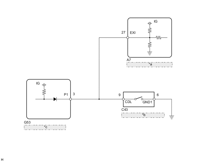
| *a | Skid Control ECU (Master Cylinder Solenoid) |
| *b | Center Differential Lock Detection Switch (Transfer Shift Actuator) |
| *c | 4 Wheel Drive Control ECU |
PROCEDURE
-
CHECK DTC
-
Check for DTCs Click here.
Result Result Proceed to DTC C1340 is not output A DTC C1340 is output B
B 
GO TO DTC C1340 Click here
A 
-
-
CHECK TEST MODE DTC
-
Switch the vehicle to test mode, perform the center differential lock signal check, and then check that the Test Mode (Signal Check) DTC C1282 is cleared Click here.
Result Result Proceed to Test Mode DTC C1282 is not cleared A Test Mode DTC C1282 is cleared B
B
USE SIMULATION METHOD TO CHECK Click here
A
-
-
CHECK HARNESS AND CONNECTOR (MASTER CYLINDER SOLENOID - 4 WHEEL DRIVE CONTROL ECU/TRANSFER SHIFT ACTUATOR ASSEMBLY)
-
Disconnect the A7 skid control ECU (master cylinder solenoid) connector.
-
Disconnect the G53 4 wheel drive control ECU connector.
-
Disconnect the C43 center differential lock detection switch (transfer shift actuator assembly) connector.
-
Measure the resistance according to the value(s) in the table below.
Standard Resistance Tester Connection Condition Specified Condition A7-27 (EXI) - G53-3 (P1) Always Below 1 Ω A7-27 (EXI) - C43-9 (CDL) Always Below 1 Ω A7-27 (EXI) - Body ground Always 10 kΩ or higher C43-6 (GND1) - Body ground Always Below 1 Ω
OK
GO TO TRANSFER SYSTEM (PROBLEM SYMPTOMS TABLE) Click here
NG
REPAIR OR REPLACE HARNESS OR CONNECTOR
-