FRONT UPPER SUSPENSION ARM INSTALLATION

CAUTION / NOTICE / HINT
Tech Tips
-
Use the same procedure for the RH and LH sides.
-
The procedure listed below is for the LH side.
-
A bolt without a torque specification is shown in the standard bolt chart Click here.
PROCEDURE
-
TEMPORARILY INSTALL FRONT SUSPENSION UPPER ARM ASSEMBLY LH
-
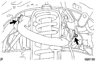
Temporarily install the suspension upper arm and 2 washers with the bolt and nut.
Tech Tips
After stabilizing the suspension, tighten the nut.
-
Connect the bracket with the bolt.
- Torque:
- 8.0 N*m { 82 kgf*cm, 71 in.*lbf }
-
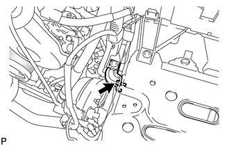
Install a new nut and clip.
- Torque:
- 110 N*m { 1122 kgf*cm, 81 ft.*lbf }
-
-
INSTALL SKID CONTROL SENSOR WIRE
-
INSTALL FRONT WHEEL
- Torque:
- for Aluminum Wheel
- 103 N*m { 1050 kgf*cm, 76 ft.*lbf }
- for Steel Wheel
- 112 N*m { 1137 kgf*cm, 82 ft.*lbf }
-
STABILIZE SUSPENSION
-
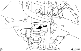
TIGHTEN FRONT SUSPENSION UPPER ARM ASSEMBLY LH
-
Tighten the nut.
- Torque:
- 115 N*m { 1173 kgf*cm, 85 ft.*lbf }
-
-
INSPECT AND ADJUST FRONT WHEEL ALIGNMENT
-
Inspect and adjust the front wheel alignment Click here.
-