FRONT STABILIZER BAR(w/o KDSS) INSTALLATION
PROCEDURE
-
INSTALL FRONT STABILIZER BAR
-
INSTALL FRONT NO. 1 STABILIZER BAR BUSH
-
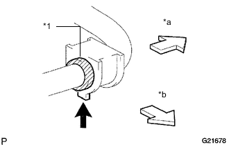
Text in Illustration *1 Bushing Stopper *a Outer Side *b Front Side 
Protrusion Install the 2 front No. 1 stabilizer bar bushes.
Tech Tips
-
Install the bush to the inner side of the bushing stopper on the stabilizer bar.
-
Install the No. 1 stabilizer bush with the protrusion facing inward.
-
-
-
INSTALL FRONT NO. 1 STABILIZER BRACKET LH
-
Install the front No. 1 stabilizer bracket LH with the 2 bolts.
- Torque:
- 49 N*m { 500 kgf*cm, 36 ft.*lbf }
-
-
INSTALL FRONT NO. 1 STABILIZER BRACKET RH
Tech Tips
Use the same procedure described for the LH side.
-
INSTALL FRONT STABILIZER LINK ASSEMBLY LH
-
Install the front stabilizer link assembly LH with the 2 nuts.
- Torque:
- 70 N*m { 714 kgf*cm, 52 ft.*lbf }
Tech Tips
If the ball joint turns together with the nut, use a 6 mm hexagon wrench to hold the stud.
-
-
INSTALL FRONT STABILIZER LINK ASSEMBLY RH
Tech Tips
Use the same procedure described for the LH side.
-
INSTALL FRONT SUSPENSION MEMBER BRACE SUB-ASSEMBLY
-
INSTALL NO. 1 ENGINE UNDER COVER SUB-ASSEMBLY
-
INSTALL LOWER FRONT BUMPER COVER
-
INSTALL FRONT WHEEL
- Torque:
- for Aluminum Wheel
- 103 N*m { 1050 kgf*cm, 76 ft.*lbf }
- for Steel Wheel
- 112 N*m { 1137 kgf*cm, 82 ft.*lbf }