STABILIZER CONTROL TUBE(w/ KDSS) INSTALLATION
PROCEDURE
-
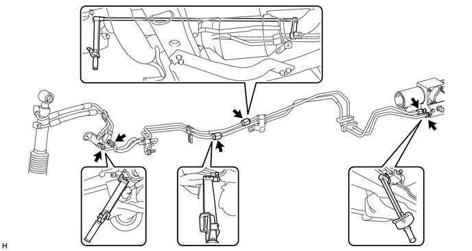
INSTALL FRONT NO. 1 STABILIZER CONTROL TUBE ASSEMBLY
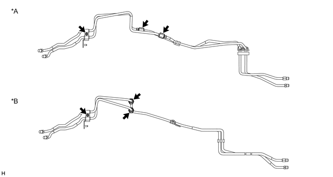
Text in Illustration *A for 1GR-FE *B for 1KD-FTV, 1GD-FTV
-
Using a union nut wrench, disconnect the 2 flare nuts of a new front No. 1 stabilizer control tube assembly.
-
Remove the bolt and clamp from the front No. 1 stabilizer control tube assembly.
-
Disassemble the front No. 1 stabilizer control tube assembly.
-
Pull the front No. 1 stabilizer control tube assembly (upper part) and front No. 1 stabilizer control tube assembly (lower part) through the vehicle.
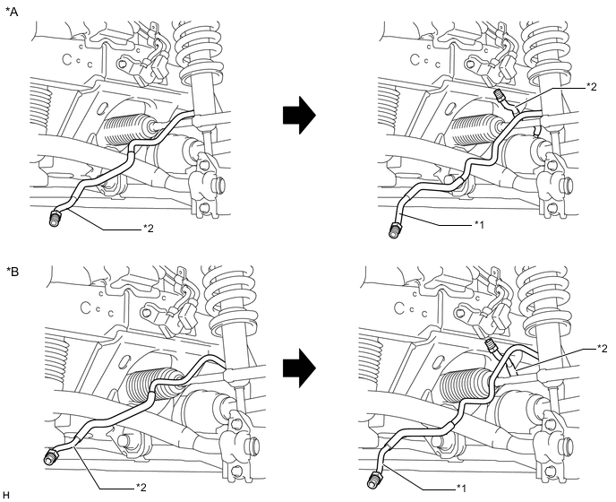
Text in Illustration *A for 1GR-FE *B for 1KD-FTV, 1GD-FTV *1 Front No. 1 Stabilizer Control Tube Assembly (Upper Part) *2 Front No. 1 Stabilizer Control Tube Assembly (Lower Part) -
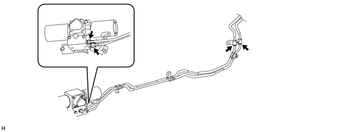
Temporarily install the 2 flare nuts on the front No. 1 stabilizer control tube assembly (front stabilizer with tube cylinder assembly side).
Text in Illustration *A for 1GR-FE *B for 1KD-FTV, 1GD-FTV -
Install the clamp to the front No. 1 stabilizer control tube assembly with the bolt (labeled A).
-
Connect the clamp to the body with the bolt (labeled B).
- Torque:
- 29 N*m { 296 kgf*cm, 21 ft.*lbf }
-
Temporarily install the 4 flare nuts on the disconnected end of the front No. 1 stabilizer control tube assembly (stabilizer control with accumulator housing side).
Text in Illustration *A for 1GR-FE *B for 1KD-FTV, 1GD-FTV -
Connect the clamp to the body with the bolt.
-
for 1GR-FE:
Tighten the 6 flare nuts on the front No. 1 stabilizer control tube assembly.
- Torque:
- 44 N*m { 450 kgf*cm, 33 ft.*lbf }
Note
Use the formula to calculate special torque values for situations where a union nut wrench is combined with a torque wrench Click here.
-
for 1KD-FTV, 1GD-FTV:
Tighten the 6 flare nuts on the front No. 1 stabilizer control tube assembly.
- Torque:
- 44 N*m { 450 kgf*cm, 33 ft.*lbf }
Note
Use the formula to calculate special torque values for situations where a union nut wrench is combined with a torque wrench Click here.
-
-
INSTALL FRONT STABILIZER TUBE PROTECTOR
-
Install the front stabilizer tube protector with the 2 bolts.
- Torque:
- 29 N*m { 296 kgf*cm, 21 ft.*lbf }
-
-
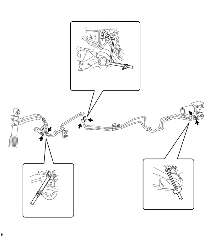
INSTALL REAR NO. 1 STABILIZER CONTROL TUBE ASSEMBLY
-
Disconnect the 2 flare nuts of a new rear No. 1 stabilizer control tube assembly.
-
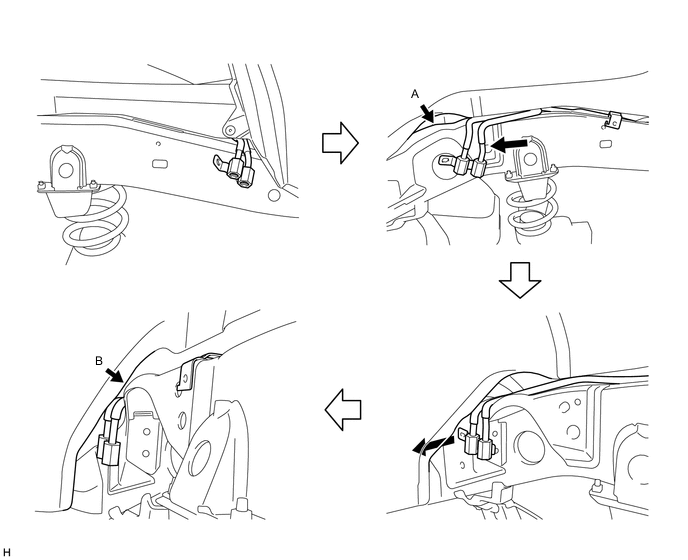
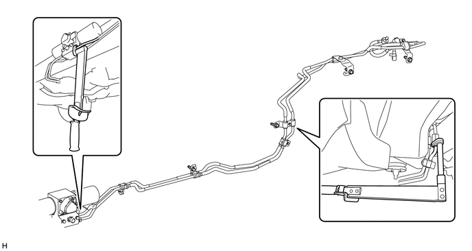
Move the rear No. 1 stabilizer control tube assembly (rear stabilizer control cylinder side) towards the outside of the frame.
-
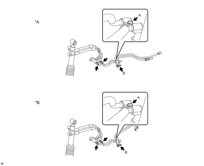
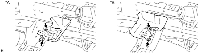
Using a plastic-faced hammer, lightly tap the rear No. 1 stabilizer control tube assembly (rear stabilizer control cylinder side) and slide it to the left.
Note
-
Make sure that the rear No. 1 stabilizer control tube assembly is not deformed, as the gaps shown by arrows A and B in the illustration are small.
-
Slide the rear No. 1 stabilizer control tube assembly to the left so that the flare nut part is between the frame and wheel house.
-
If the flare nut part protrudes on the wheel house side, move the part back to the rear of the vehicle and slide it once again to install it.
-
-
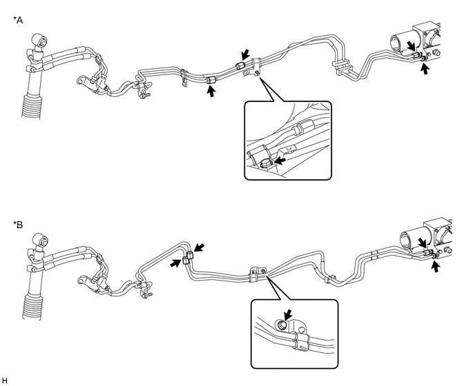
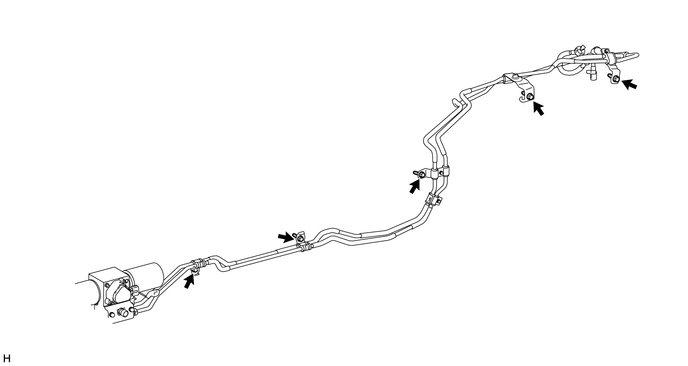
Temporarily install the 4 flare nuts on the disconnected end of the rear No. 1 stabilizer control tube assembly (stabilizer control with accumulator housing side).
-
Install the rear No. 1 stabilizer control tube assembly with the 5 bolts.
- Torque:
- 29 N*m { 296 kgf*cm, 21 ft.*lbf }
-
Tighten the 4 flare nuts on the rear No. 1 stabilizer control tube assembly.
- Torque:
- 44 N*m { 450 kgf*cm, 33 ft.*lbf }
Note
Use the formula to calculate special torque values for situations where a union nut wrench is combined with a torque wrench Click here.
-
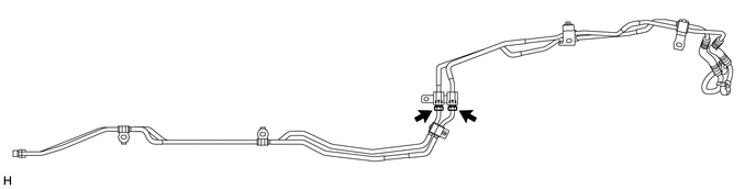
Install the rear stabilizer control tubes to the rear stabilizer control cylinder with the 2 union bolts and 2 new pressure port gaskets.
- Torque:
- 48 N*m { 484 kgf*cm, 35 ft.*lbf }
Note
Insert the stoppers of the rear stabilizer control tubes into the rear stabilizer control cylinder.
-
-
INSTALL REAR SHOCK ABSORBER ASSEMBLY LH
-
INSTALL FUEL PUMP CONTROL ECU ASSEMBLY
-
BLEED AIR FROM SUSPENSION FLUID
-
APPLY PRESSURE ACCORDING TO TEMPERATURE MANAGEMENT CHART WHEN FILLING FLUID
-
INSPECT FOR SUSPENSION FLUID LEAK
-
INSTALL FRONT WHEEL
- Torque:
- 112 N*m { 1142 kgf*cm, 83 ft.*lbf }
-
INSTALL REAR WHEEL
- Torque:
- 112 N*m { 1142 kgf*cm, 83 ft.*lbf }
-
INSTALL SPARE TIRE
-
MEASURE VEHICLE HEIGHT
-
INSTALL TRANSMISSION UNDER COVER
-
INSTALL NO. 1 ENGINE UNDER COVER SUB-ASSEMBLY
-
INSTALL FRONT BUMPER COVER LOWER
-
INSTALL UREA PUMP CONTROL ECU (for 1GD-FTV)
-
INSTALL STABILIZER CONTROL VALVE PROTECTOR
-
Install the stabilizer control valve protector with the 2 bolts.
- Torque:
- 29 N*m { 296 kgf*cm, 21 ft.*lbf }
Text in Illustration *A for 1GR-FE *B for 1KD-FTV
-
-
INSTALL SIDE STEP ASSEMBLY LH
-
CONNECT CABLE TO NEGATIVE BATTERY TERMINAL
Note
When disconnecting the cable, some systems need to be initialized after the cable is reconnected Click here.