STABILIZER CONTROL VALVE(w/ KDSS) INSTALLATION
PROCEDURE
-
INSTALL STABILIZER CONTROL WITH ACCUMULATOR HOUSING ASSEMBLY
-
Install the stabilizer control with accumulator housing with the 3 bolts.
- Torque:
- 29 N*m { 296 kgf*cm, 21 ft.*lbf }
-
Connect the connector, and then attach the clamp to the hole of the bracket.
-
-
CONNECT FRONT NO. 1 STABILIZER CONTROL TUBE ASSEMBLY
-
Temporarily install the 2 flare nuts on the front No. 1 stabilizer control tube assembly.
-
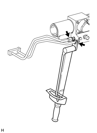
Using a union nut wrench, tighten the 2 flare nuts on the front No. 1 stabilizer control tube assembly.
- Torque:
- 44 N*m { 450 kgf*cm, 33 ft.*lbf }
Note
Use the formula to calculate special torque values for situations where a union nut wrench is combined with a torque wrench Click here.
-
-
CONNECT REAR NO. 1 STABILIZER CONTROL TUBE ASSEMBLY
-
Temporarily install the 2 flare nuts on the rear No. 1 stabilizer control tube assembly.
-
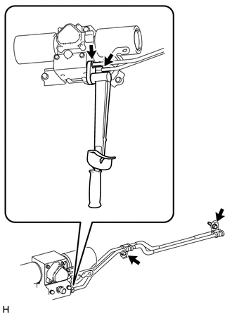
Connect the rear No. 1 stabilizer control tube assembly with the 2 bolts.
- Torque:
- 29 N*m { 296 kgf*cm, 21 ft.*lbf }
-
Using a union nut wrench, tighten the 2 flare nuts on the rear stabilizer control tubes.
- Torque:
- 44 N*m { 450 kgf*cm, 33 ft.*lbf }
Note
Use the formula to calculate special torque values for situations where a union nut wrench is combined with a torque wrench Click here.
-
-
BLEED AIR FROM SUSPENSION FLUID
-
APPLY PRESSURE ACCORDING TO TEMPERATURE MANAGEMENT CHART WHEN FILLING FLUID
-
INSPECT FOR SUSPENSION FLUID LEAK
-
MEASURE VEHICLE HEIGHT
-
INSTALL STABILIZER CONTROL VALVE PROTECTOR
-
Install the stabilizer control valve protector with the 2 bolts.
- Torque:
- 29 N*m { 296 kgf*cm, 21 ft.*lbf }
-
-
INSTALL SIDE STEP ASSEMBLY LH
-
CONNECT CABLE TO NEGATIVE BATTERY TERMINAL
Note
When disconnecting the cable, some systems need to be initialized after the cable is reconnected Click here.