KINETIC DYNAMIC SUSPENSION SYSTEM, Diagnostic DTC:C1882/82
| DTC Code | DTC Name |
|---|---|
| C1882/82 | Power Supply Voltage Malfunction |
DESCRIPTION
The stabilizer control ECU recognizes the ignition switch ON signal based on the voltage input to the IG terminal.
| DTC Code | DTC Detection Condition | Trouble Area |
|---|---|---|
| C1882/82 | The IG terminal voltage is 10 V or less or 16 V or higher for 0.5 seconds |
|
WIRING DIAGRAM
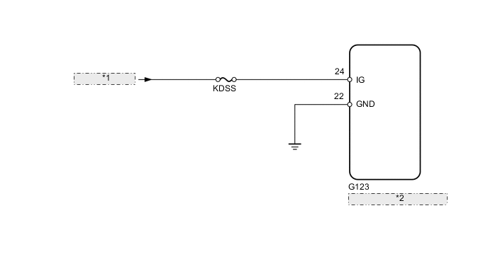
| *1 | from IG Circuit |
| *2 | Stabilizer Control ECU |
CAUTION / NOTICE / HINT
Note
Inspect the fuses for circuits related to this system before performing the following inspection procedure.
PROCEDURE
-
READ VALUE USING INTELLIGENT TESTER (IG POWER SOURCE VOLTAGE)
-
Turn the ignition switch off.
-
Connect the intelligent tester to the DLC3.
-
Turn the ignition switch to ON.
-
Turn the intelligent tester on.
-
Enter the following menus: Chassis / KDSS / Data List.
-
Select the item below in the Data List, and read the value displayed on the intelligent tester.
KDSS Tester Display Measurement Item/Range Normal Condition Diagnostic Note IG Power Source Voltage IG Power Source Voltage/
Min.: 0.0 V
Max.: 25.5 V
Ignition switch ON: 11 to 14 V - Standard voltage 11 to 14 V
NG 
CHECK HARNESS AND CONNECTOR (IG TERMINAL) Click here
OK 
-
-
RECONFIRM DTC
-
Clear the DTCs Click here.
-
Check for DTCs Click here.
Result Result Proceed to DTC is output A DTC is not output B
A 
REPLACE STABILIZER CONTROL ECU Click here
B
USE SIMULATION METHOD TO CHECK Click here
-
-
CHECK HARNESS AND CONNECTOR (IG TERMINAL)
-
Disconnect the Stabilizer control ECU connector.
-
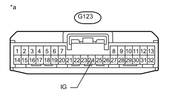
Text in Illustration *a Front view of wire harness connector
(to Stabilizer Control ECU)
Measure the voltage according to the value(s) in the table below.
Standard Voltage Tester Connection Switch Condition Specified Condition G123-24 (IG) - Body ground Ignition switch ON 11 to 14 V
NG
REPAIR OR REPLACE HARNESS OR CONNECTOR
OK
-
-
CHECK HARNESS AND CONNECTOR (GND TERMINAL)
-
Disconnect the Stabilizer control ECU connector.
-
Measure the resistance according to the value(s) in the table below.
Standard Resistance Tester Connection Condition Specified Condition G123-22 (GND) - Body ground Always Below 1 Ω
OK
REPLACE STABILIZER CONTROL ECU Click here
NG
REPAIR OR REPLACE HARNESS OR CONNECTOR
-