AIR SUSPENSION SYSTEM, Diagnostic DTC:C1731/31, C1732/32, C1733/33, C1734/34

| DTC Code | DTC Name |
|---|---|
| C1731/31 | FR Damping Force Control Actuator Circuit |
| C1732/32 | FL Damping Force Control Actuator Circuit |
| C1733/33 | RR Damping Force Control Actuator Circuit |
| C1734/34 | RL Damping Force Control Actuator Circuit |
DESCRIPTION
The absorber control actuator switches the damping force depending on the suspension control ECU signals.
| DTC Code | DTC Detection Condition | Trouble Area |
|---|---|---|
| C1731/31 | Either condition is met:
|
|
| C1732/32 | Either condition is met:
|
|
| C1733/33 | Either condition is met:
|
|
| C1734/34 | Either condition is met:
|
|
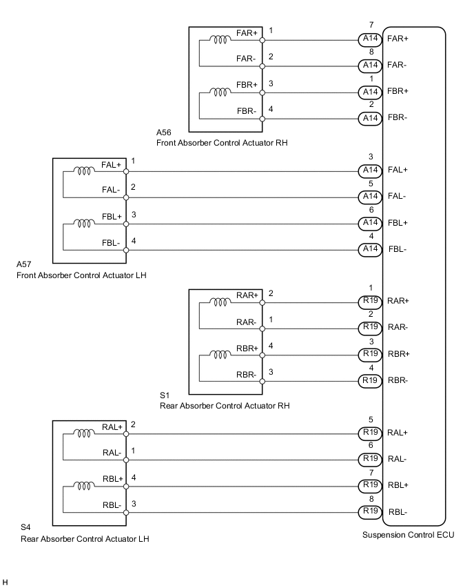
WIRING DIAGRAM
CAUTION / NOTICE / HINT
Note
When replacing the suspension control ECU, perform registration Click here.
PROCEDURE
-
PERFORM ACTIVE TEST USING INTELLIGENT TESTER (DAMPER STEP)
-
Turn the ignition switch off.
-
Connect the intelligent tester to the DLC3.
-
Turn the ignition switch to ON.
-
Turn the intelligent tester on.
-
Enter the following menus: Chassis / Air suspension / Active Test.
Air Suspension Tester Display Test Part Control Range Diagnostic Note Damper Step FR Changes damper step (Front RH) 1 to 17 step The shock absorber hardens as the damper step increases. Damper Step FL Changes damper step (Front LH) 1 to 17 step The shock absorber hardens as the damper step increases. Damper Step RR Changes damper step (Rear RH) 1 to 17 step The shock absorber hardens as the damper step increases. Damper Step RL Changes damper step (Rear LH) 1 to 17 step The shock absorber hardens as the damper step increases. OK The absorber control actuator operates.
OK 
USE SIMULATION METHOD TO CHECK Click here
NG 
-
-
INSPECT ABSORBER CONTROL ACTUATOR
-
Turn the ignition switch off.
-
Check the front absorber control actuator RH (when DTC C1731/31 is output).
-
Disconnect the A56 actuator connector.
-
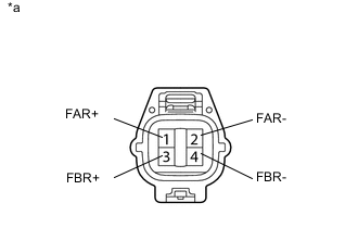
Text in Illustration *a Component without harness connected
(Front Absorber Control Actuator RH)
Measure the resistance according to the value(s) in the table below.
Standard Resistance Tester Connection Condition Specified Condition 1 (FAR+) - 2 (FAR-) Always 6.4 to 7.2 Ω 3 (FBR+) - 4 (FBR-) Always 6.4 to 7.2 Ω
-
-
Check the front absorber control actuator LH (when DTC C1732/32 is output).
-
Disconnect the A57 actuator connector.
-

Text in Illustration *a Component without harness connected
(Front Absorber Control Actuator LH)
Measure the resistance according to the value(s) in the table below.
Standard Resistance Tester Connection Condition Specified Condition 1 (FAL+) - 2 (FAL-) Always 6.4 to 7.2 Ω 3 (FBL+) - 4 (FBL-) Always 6.4 to 7.2 Ω
-
-
Check the rear absorber control actuator RH (when DTC C1733/33 is output).
-
Disconnect the S1 actuator connector.
-
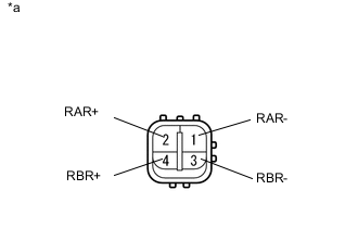
Text in Illustration *a Component without harness connected
(Rear Absorber Control Actuator RH)
Measure the resistance according to the value(s) in the table below.
Standard Resistance Tester Connection Condition Specified Condition 1 (RAR-) - 2 (RAR+) Always 6.4 to 7.2 Ω 3 (RBR-) - 4 (RBR+) Always 6.4 to 7.2 Ω
-
-
Check the rear absorber control actuator LH (when DTC C1734/34 is output).
-
Disconnect the S4 actuator connector.
-

Text in Illustration *a Component without harness connected
(Rear Absorber Control Actuator LH)
Measure the resistance according to the value(s) in the table below.
Standard Resistance Tester Connection Condition Specified Condition 1 (RAL-) - 2 (RAL+) Always 6.4 to 7.2 Ω 3 (RBL-) - 4 (RBL+) Always 6.4 to 7.2 Ω Result Result Proceed to OK A NG (Front absorber control actuator RH) B NG (Front absorber control actuator LH) C NG (Rear absorber control actuator RH) D NG (Rear absorber control actuator LH) E
-
B
REPLACE FRONT ABSORBER CONTROL ACTUATOR RH Click here
C
REPLACE FRONT ABSORBER CONTROL ACTUATOR LH Click here
D
REPLACE REAR SHOCK ABSORBER ASSEMBLY RH Click here
E
REPLACE REAR SHOCK ABSORBER ASSEMBLY LH Click here
A
-
-
CHECK HARNESS AND CONNECTOR (ABSORBER CONTROL ACTUATOR - SUSPENSION CONTROL ECU)
-
Check the front side absorber control actuator.
-
Disconnect the A56 and/or A57 front absorber control actuator connector.
-
Disconnect the A14 suspension control ECU connector.
-
Measure the resistance according to the value(s) in the table below.
Standard Resistance for Front RH (for DTC C1731/31) Tester Connection Condition Specified Condition A56-1 (FAR+) - A14-7 (FAR+) Always Below 1 Ω A56-2 (FAR-) - A14-8 (FAR-) Always Below 1 Ω A56-3 (FBR+) - A14-1 (FBR+) Always Below 1 Ω A56-4 (FBR-) - A14-2 (FBR-) Always Below 1 Ω A56-1 (FAR+) - Body ground Always 10 kΩ or higher A56-2 (FAR-) - Body ground Always 10 kΩ or higher A56-3 (FBR+) - Body ground Always 10 kΩ or higher A56-4 (FBR-) - Body ground Always 10 kΩ or higher for Front LH (for DTC C1732/32) Tester Connection Condition Specified Condition A57-1 (FAL+) - A14-3 (FAL+) Always Below 1 Ω A57-2 (FAL-) - A14-5 (FAL-) Always Below 1 Ω A57-3 (FBL+) - A14-6 (FBL+) Always Below 1 Ω A57-4 (FBL-) - A14-4 (FBL-) Always Below 1 Ω A57-1 (FAL+) - Body ground Always 10 kΩ or higher A57-2 (FAL-) - Body ground Always 10 kΩ or higher A57-3 (FBL+) - Body ground Always 10 kΩ or higher A57-4 (FBL-) - Body ground Always 10 kΩ or higher
-
-
Check the rear side absorber control actuator.
-
Disconnect the S1 and/or S4 rear absorber control actuator connector.
-
Disconnect the R19 suspension control ECU connector.
-
Measure the resistance according to the value(s) in the table below.
Standard Resistance for Rear RH (for DTC C1733/33) Tester Connection Condition Specified Condition S1-1 (RAR-) - R19-2 (RAR-) Always Below 1 Ω S1-2 (RAR+) - R19-1 (RAR+) Always Below 1 Ω S1-3 (RBR-) - R19-4 (RBR-) Always Below 1 Ω S1-4 (RBR+) - R19-3 (RBR+) Always Below 1 Ω S1-1 (RAR-) - Body ground Always 10 kΩ or higher S1-2 (RAR+) - Body ground Always 10 kΩ or higher S1-3 (RBR-) - Body ground Always 10 kΩ or higher S1-4 (RBR+) - Body ground Always 10 kΩ or higher for Rear LH (for DTC C1734/34) Tester Connection Condition Specified Condition S4-1 (RAL-) - R19-6 (RAL-) Always Below 1 Ω S4-2 (RAL+) - R19-5 (RAL+) Always Below 1 Ω S4-3 (RBL-) - R19-8 (RBL-) Always Below 1 Ω S4-4 (RBL+) - R19-7 (RBL+) Always Below 1 Ω S4-1 (RAL-) - Body ground Always 10 kΩ or higher S4-2 (RAL+) - Body ground Always 10 kΩ or higher S4-3 (RBL-) - Body ground Always 10 kΩ or higher S4-4 (RBL+) - Body ground Always 10 kΩ or higher
-
OK
REPLACE SUSPENSION CONTROL ECU Click here
NG
REPAIR OR REPLACE HARNESS OR CONNECTOR
-