AIR SUSPENSION SYSTEM, Diagnostic DTC:C1752

| DTC Code | DTC Name |
|---|---|
| C1752 | Compressor Motor Malfunction |
DESCRIPTION
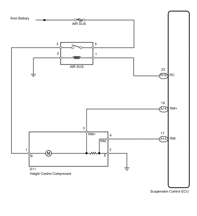
When the "up" side of the height control switch is pressed, a signal is sent from terminal RC of the suspension control ECU to switch the AIR SUS relay on. As a result, the relay contacts close and the compressor motor turns on, producing compressed air.
The suspension control ECU detects the amount of current flowing to the compressor motor by means of the differences in potential at terminals RM+ and RM- of the suspension control ECU. In this way, the suspension control ECU monitors the compressor motor circuit for abnormalities.
| DTC Code | DTC Detection Condition | Trouble Area |
|---|---|---|
| C1752 | With the AIR SUS relay activated, a lock signal of the height control compressor motor is detected for 4 seconds or more. |
|
WIRING DIAGRAM
CAUTION / NOTICE / HINT
Note
-
When replacing the suspension control ECU, perform registration Click here.
-
Inspect the fuses for circuits related to this system before performing the following inspection procedure.
Tech Tips
If DTC C1782 is output at the same time as C1752, perform the inspection necessary for DTC C1782 first Click here.
PROCEDURE
-
INSPECT SUSPENSION CONTROL RELAY (AIR SUS)
NG 
REPLACE SUSPENSION CONTROL RELAY (AIR SUS)
OK 
-
CHECK TERMINAL VOLTAGE (POWER SUPPLY)
-
Remove the AIR SUS relay from the engine room relay block.
-
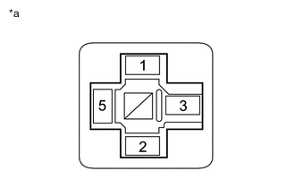
Text in Illustration *a Component without AIR SUS Relay
(Engine Room Relay Block)
Measure the voltage according to the value(s) in the table below.
Standard Voltage Tester Connection Condition Specified Condition Engine room relay block AIR SUS relay terminal 5 - Body ground Always 11 to 14 V
NG
REPAIR OR REPLACE HARNESS OR CONNECTOR
OK
-
-
CHECK HARNESS AND CONNECTOR (HEIGHT CONTROL COMPRESSOR - AIR SUS RELAY/SUSPENSION CONTROL ECU)
-
Disconnect the S11 height control compressor connector.
-
Remove the AIR SUS relay from the engine room relay block.
-
Disconnect the A14 suspension control ECU connector.
-
Measure the resistance according to the value(s) in the table below.
Standard Resistance Tester Connection Condition Specified Condition S11-1 (B) - Engine room relay block AIR SUS relay terminal 3 Always Below 1 Ω S11-1 (B) - Body ground Always 10 kΩ or higher S11-2 (E) - Body ground Always Below 1 Ω A14-19 (RM+) - S11-3 (RM+) Always Below 1 Ω A14-19 (RM+) - Body ground Always 10 kΩ or higher A14-17 (RM-) - S11-4 (RM-) Always Below 1 Ω A14-17 (RM-) - Body ground Always 10 kΩ or higher
NG
REPAIR OR REPLACE HARNESS OR CONNECTOR
OK
-
-
INSPECT HEIGHT CONTROL COMPRESSOR (COMPRESSOR MOTOR)
-
Remove the height control compressor Click here.
-
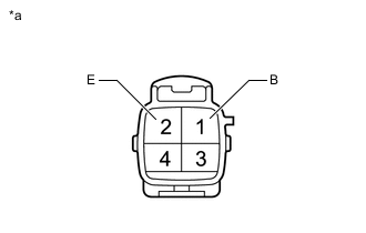
Text in Illustration *a Component without harness connected
(Height Control Compressor)
Apply 12 V battery voltage to the compressor motor and check the operation of the motor.
OK Measurement Condition Specified Condition 12 V battery positive (+) voltage → Terminal 1 (B)
12 V battery negative (-) voltage → Terminal 2 (E)
Motor operates Note
-
Do not allow the compressor motor to operate for approximately 90 seconds or more.
-
If the compressor is shorted, locked or has a similar type of malfunction, a large amount of current is flowing. Therefore, if the motor does not operate, immediately stop this inspection.
-
OK
REPLACE SUSPENSION CONTROL ECU Click here
NG
REPLACE HEIGHT CONTROL COMPRESSOR ASSEMBLY Click here
-