DIFFERENTIAL SYSTEM(w/ Differential Lock) Shift Motor Circuit
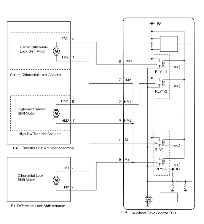
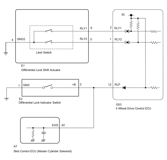
WIRING DIAGRAM
PROCEDURE
-
INSPECT DIFFERENTIAL LOCK SHIFT ACTUATOR (DIFFERENTIAL LOCK SHIFT MOTOR)
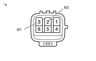
Text in Illustration *a Component without harness connected
(Center Differential Lock Actuator)
-
Disconnect the E1 differential lock shift actuator connector.
-
Measure the resistance according to the value(s) in the table below.
Standard Resistance Tester Connection Condition Specified Condition 3 (M1) - 2 (M2) Always 1.5 to 100 Ω
NG 
REPLACE DIFFERENTIAL LOCK SHIFT ACTUATOR Click here
OK 
-
-
CHECK HARNESS AND CONNECTOR (4 WHEEL DRIVE CONTROL ECU - DIFFERENTIAL LOCK SHIFT ACTUATOR)
-
Disconnect the G54 4 wheel drive control ECU connector.
-
Disconnect the E1 differential lock shift actuator connector.
-
Measure the resistance according to the value(s) in the table below.
Standard Resistance Tester Connection Condition Specified Condition G54-3 (M1) - E1-3 (M1) Always Below 1 Ω G54-9 (M2) - E1-2 (M2) Always Below 1 Ω G54-3 (M1) or E1-3 (M1) - G54-9 (M2) or E1-2 (M2) Always 10 kΩ or higher
NG
REPAIR OR REPLACE HARNESS OR CONNECTOR
OK
-
-
CHECK HARNESS AND CONNECTOR (4 WHEEL DRIVE CONTROL ECU - DIFFERENTIAL LOCK SHIFT ACTUATOR AND NO. 1 TRANSFER INDICATOR SWITCH)
-
Disconnect the G53 4 wheel drive control ECU connector.
-
Disconnect the E1 differential lock shift actuator connector.
-
Disconnect the E2 differential lock indicator switch connector.
-
Disconnect the A7 skid control ECU (master cylinder solenoid) connector.
-
Measure the resistance according to the value(s) in the table below.
Standard Resistance Tester Connection Condition Specified Condition G53-2 (RLY1) - E1-6 (RLY1) Always Below 1 Ω G53-1 (RLY2) - E1-5 (RLY2) Always Below 1 Ω E1-4 (GND2) - Body ground Always Below 1 Ω G53-12 (RLP) - E2-2 (+B) Always Below 1 Ω E2-1 (GND) - Body ground Always Below 1 Ω G53-2 (RLY1) or E1-6 (RLY1) - Body ground Always 10 kΩ or higher G53-1 (RLY2) or E1-5 (RLY2) - Body ground Always 10 kΩ or higher G53-12 (RLP) or E2-2 (+B) - Body ground Always 10 kΩ or higher
NG
REPAIR OR REPLACE HARNESS OR CONNECTOR
OK
-
-
INSPECT DIFFERENTIAL LOCK SHIFT ACTUATOR (LIMIT SWITCH)
-
Turn the ignition switch off.
-
Remove the differential lock shift actuator Click here.
-
Check the limit switch of the differential lock shift actuator Click here.
NG
REPLACE DIFFERENTIAL LOCK SHIFT ACTUATOR Click here
OK
-
-
INSPECT DIFFERENTIAL LOCK INDICATOR SWITCH
-
Turn the ignition switch off.
-
Remove the differential lock indicator switch Click here.
-
Check the differential lock indicator switch Click here.
OK The differential lock indicator switch is normally.
OK
REPLACE 4 WHEEL DRIVE CONTROL ECU Click here
NG
REPLACE DIFFERENTIAL LOCK INDICATOR SWITCH Click here
-