DIFFERENTIAL SYSTEM(w/ Differential Lock) TERMINALS OF ECU
-
CHECK 4 WHEEL DRIVE CONTROL ECU
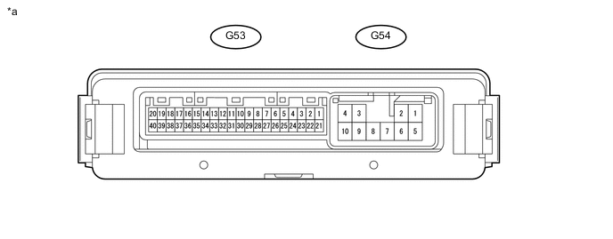
*a Component with harness connected
(4 Wheel Drive Control ECU)
- -
-
Measure the voltage and resistance according to the value(s) in the table below.
Terminal No. (Symbol) Wiring Color Terminal Description Condition Specified Condition G53-1 (RLY2) - G54-10 (GND) P - W-B Limit switch of differential lock shift actuator input Ignition switch ON
Rear differential not free
Below 1.5 V Ignition switch ON
Rear differential free
11 to 14 V G53-2 (RLY1) - G54-10 (GND) G - W-B Limit switch of differential lock shift actuator input Ignition switch ON
Rear differential not lock
Below 1.5 V Ignition switch ON
Rear differential lock
11 to 14 V G53-12 (RLP) - G54-10 (GND) V - W-B Differential lock indicator switch input Ignition switch ON
Differential lock indicator switch ON (When rear differential lock)
Below 1.5 V Ignition switch ON
Differential lock indicator switch OFF (When rear differential free)
9.5 to 14 V G53-15 (R) - G54-10 (GND) R - W-B Differential lock switch input Ignition switch ON
Rear differential lock switch on
Below 1.5 V Ignition switch ON
Rear differential lock switch off
11 to 14 V G53-20 (CANH) - G53-40 (CANL) G - W CAN communication line Ignition switch off
Cable disconnected from negative (-) battery terminal
54 to 69 Ω G53-21 (+B) - G54-10 (GND) W - W-B ECU power supply Always 11 to 14 V G54-3 (M1) - G54-10 (GND) B - W-B Differential lock shift motor output Ignition switch ON
Transfer low and center differential lock
Differential lock switch switched from off (free) to on (lock)
(Switching rear differential from free to lock)
(After the transfer system switches from free to locked, 5 seconds elapse after communication starts or limit switch switching completes)
11 to 14 V Ignition switch ON
Transfer low and center differential lock
Differential lock switch switched from on (lock) to off (free) or transfer position switch switched from L4 to H4
(Switching rear differential from lock to free)
Below 1.5 V G54-4 (IG) - G54-10 (GND) R - W-B IG power Ignition switch ON 11 to 14 V G54-9 (M2) - G54-10 (GND) Y - W-B Differential lock actuator motor Ignition switch ON
Transfer low and center differential lock
Differential lock switch switched from off (free) to on (lock)
(Switching rear differential from free to lock)
Below 1.5 V Ignition switch ON
Transfer low and center differential lock
Differential lock switch switched from on (lock) to off (free) or transfer position switch switched from L4 to H4
(Switching rear differential from lock to free)
(After the transfer system switches from locked to free, 5 seconds elapse after communication starts or limit switch switching completes)
11 to 14 V G54-10 (GND) - Body ground W-B - Body ground Ground Always Below 1 Ω
-