DIFFERENTIAL SYSTEM INSPECTION
PROCEDURE
-
INSPECT DIFFERENTIAL LOCK SYSTEM
-
Inspect the indicator light.
-
Check that the indicator light lights up approximately 1 second after the ignition switch is turned to ON.
-
-
Inspect the differential lock operation.
-
Jack up the vehicle and start the engine.
-
Set the transfer to L4 or L4L.
-
When the differential lock control switch is set to the ON position, check that the indicator light turns on. Differential lock is applied to the rear wheels at this time.
Tech Tips
If the gears of the differential lock system are not engaged, the indicator light continues blinking, so rotate the tires to engage the gears.
-
When the differential lock control switch is in the OFF position, check that the indicator light goes off. The rear differential lock is released at this time.
-
Stop the engine and lower the vehicle.
-
-
-
INSPECT FOUR WHEEL DRIVE CONTROL ECU (POWER SUPPLY)
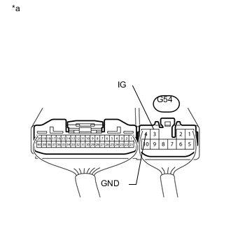
Text in Illustration *a Component with harness connected
(4 wheel drive control ECU)
-
Check the harness and connector (ECU - battery and body ground).
-
Measure the voltage according to the value(s) in the table below.
Standard Voltage Tester Connection Switch Condition Specified Condition G54-3 (IG) - Body ground Ignition switch ON 11 to 14 V If the result is not as specified, inspect the harness and connector or 4WD fuse. If the harness is malfunctioning, repair or replace the harness and connector or 4WD fuse. If the harness and connector are normal, replace the 4 wheel drive control ECU Click here.
-
Measure the resistance according to the value(s) in the table below.
Standard Resistance Tester Connection Condition Specified Condition G54-4 (GND) - Body ground Always Below 1 Ω If the result is not as specified, repair or replace the harness or connector.
-
-
-
INSPECT CENTER CLUSTER MODULE SWITCH (REAR DIFFERENTIAL LOCK CONTROL SWITCH) (w/ Combination Switch)
-
Check the harness and connector (center cluster module switch (rear differential lock control switch) - ECU).
-
Disconnect the G53 ECU connector.
-
Disconnect the G156 switch connector.
-
Measure the resistance according to the value(s) in the table below.
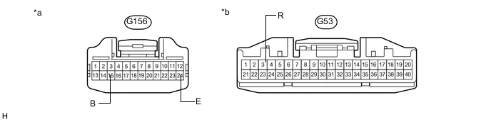
Text in Illustration *a Front view of wire harness connector
(to center cluster module switch (rear differential lock control switch))
*b Front view of wire harness connector
(to 4 wheel drive control ECU)
Standard Resistance Tester Connection Condition Specified Condition G156-15 (B) - G53-3 (R) Always Below 1 Ω G156-24 (E) - Body ground Always Below 1 Ω G156-24 (E) - G53-3 (R) Always 10 kΩ or higher If the result is not as specified, repair or replace the harness or connector.
-
-
Check the center cluster module switch (rear differential lock control switch).
-
Turn the ignition switch to ON.
-
Connect the G156 switch connector.
-
Connect the G53 ECU connector.
-
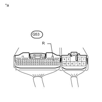
Text in Illustration *a Component with harness connected
(4 wheel drive control ECU)
Measure the voltage according to the value(s) in the table below.
Standard Voltage Tester Connection Switch Condition Specified Condition G53-3 (R) - Body ground center cluster module switch (rear differential lock control switch) on Below 1.5 V center cluster module switch (rear differential lock control switch) off 11 to 14 V
-
-
-
INSPECT DIFFERENTIAL LOCK SWITCH (w/o Combination Switch)
-
Check the harness and connector (differential lock switch - ECU).
-
Disconnect the G53 ECU connector.
-
Disconnect the G110 switch connector.
-
Measure the resistance according to the value(s) in the table below.
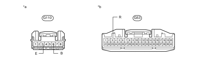
Text in Illustration *a Front view of wire harness connector
(to differential lock switch)
*b Front view of wire harness connector
(to 4 wheel drive control ECU)
Standard Resistance Tester Connection Condition Specified Condition G110-6 (B) - G53-3 (R) Always Below 1 Ω G110-3 (E) - Body ground Always Below 1 Ω G110-3 (E) - G53-3 (R) Always 10 kΩ or higher If the result is not as specified, repair or replace the harness or connector.
-
-
Check the center cluster module switch (rear differential lock control switch).
-
Turn the ignition switch to ON.
-
Connect the G110 switch connector.
-
Connect the G53 ECU connector.
-
Text in Illustration *a Component with harness connected
(4 wheel drive control ECU)
Measure the voltage according to the value(s) in the table below.
Standard Voltage Tester Connection Switch Condition Specified Condition G53-3 (R) - Body ground differential lock switch on Below 1.5 V differential lock switch off 11 to 14 V
-
-
-
INSPECT REAR DIFFERENTIAL LOCK SHIFT ACTUATOR
-
Check the harness and connector (rear differential lock actuator - ECU).
-
Disconnect the E1 differential lock actuator connector.
-
Disconnect the G53 and G54 ECU connectors.
-
Measure the resistance according to the value(s) in the table below.
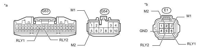
Text in Illustration *a Front view of wire harness connector
(to 4 wheel drive control ECU)
*b Front view of wire harness connector
(to Differential Lock Shift Actuator)
Standard Resistance Tester Connection Condition Specified Condition G53-10 (RLY2) - E1-5 (RLY2) Always Below 1 Ω G53-10 (RLY2) - Body ground Always 10 kΩ or higher G53-9 (RLY1) - E1-6 (RLY1) Always Below 1 Ω G53-9 (RLY1) - Body ground Always 10 kΩ or higher G54-5 (M2) - E1-2 (M2) Always Below 1 Ω G54-5 (M2) - Body ground Always 10 kΩ or higher G54-1 (M1) - E1-3 (M1) Always Below 1 Ω G54-1 (M1) - Body Ground Always 10 kΩ or higher E1-4 (GND2) - Body Ground Always Below 1 Ω
-
-
Check the free to lock switch.
-
Connect lines via a relay as shown in the illustration and check that the actuator fork moves from the free to the lock position.
Note
-
Make sure to perform this inspection with the actuator removed from the vehicle. If this inspection is performed with the actuator installed to the vehicle, the actuator will be damaged.
-
When inspecting the actuator, make sure to operate it with the lines connected via a relay. If the lines are not connected via a relay and battery voltage is directly applied to the actuator, the actuator will be damaged.
Tech Tips
When performing the operation described above, use the DEF relay.
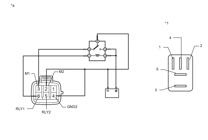
Text in Illustration *1 DEF Relay - - *a Front view of wire harness connector
(to Differential Lock Shift Actuator)
- - -
-
After the free to lock switch is complete, check the limit switch.
Measure the resistance according to the value(s) in the table below.
Standard Resistance Tester Connection Condition Specified Condition 5 (RLY2) - 4 (GND2) After free to lock switch is complete Below 12.5 Ω 6 (RLY1) - 4 (GND2) After free to lock switch is complete 500 kΩ or higher If the result is not as specified, replace the differential lock shift actuator assembly.
-
-
Check the lock to free switch.
-
Connect lines via a relay as shown in the illustration and check that the actuator fork moves from the lock to the free position.
Note
-
Make sure to perform this inspection with the actuator removed from the vehicle. If this inspection is performed with the actuator installed to the vehicle, the actuator will be damaged.
-
When inspecting the actuator, make sure to operate it with the lines connected via a relay. If the lines are not connected via a relay and battery voltage is directly applied to the actuator, the actuator will be damaged.
Tech Tips
When performing the operation described above, use the DEF relay.
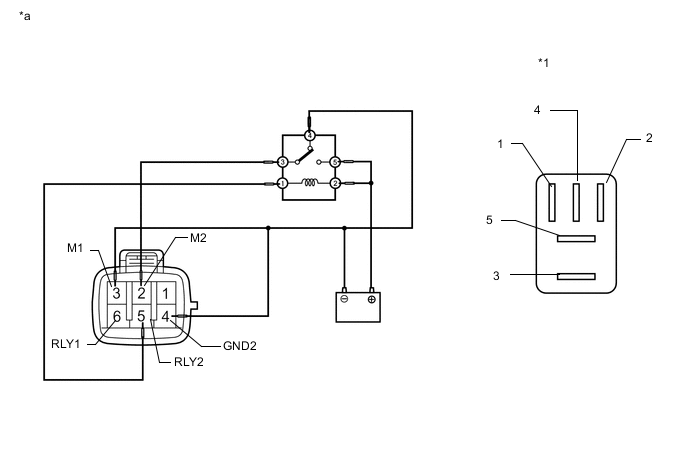
Text in Illustration *1 DEF Relay - - *a Front view of wire harness connector
(to Differential Lock Shift Actuator)
- - -
-
After the lock to free switch is complete, check the limit switch.
Measure the resistance according to the value(s) in the table below.
Standard Resistance Tester Connection Condition Specified Condition 5 (RLY2) - 4 (GND2) After lock to free switch is complete 500 kΩ or higher 6 (RLY1) - 4 (GND2) After lock to free switch is complete Below 12.5 Ω If the result is not as specified, replace the differential lock shift actuator assembly.
-
-
-
INSPECT DIFFERENTIAL LOCK POSITION SWITCH
-
Inspect the rear differential lock position switch.
-
Remove the rear differential lock position switch Click here.
-
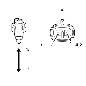
Text in Illustration *a Component without harness connected
(Rear Differential Lock Position Switch)
*b Pushed *c Released Measure the resistance according to the value(s) in the table below.
Standard Resistance Tester Connection Switch Condition Specified Condition 2 (+B) - 1 (GND) Pushed Below 1 Ω Released 10 kΩ or higher If the result is not as specified, replace the rear differential lock position switch.
-
-
Check the harness and connector (ECU - differential lock position switch).
-
Disconnect the E2 differential lock position switch connector.
-
Disconnect the G53 ECU connector.
-
Measure the resistance according to the value(s) in the table below.
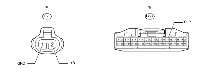
Text in Illustration *a Component without harness connected
(Rear Differential Lock Position Switch)
*b Component without harness connected
(4 wheel drive control ECU)
Standard Resistance Tester Connection Condition Specified Condition G53-15 (RLP) - E2-2 (+B) Always Below 1 Ω G53-15 (RLP) - Body ground Always 10 kΩ or higher E2-1 (GND) - Body ground Always Below 1 Ω If the result is not as specified, repair or replace the harness or connector.
-
-