REAR DIFFERENTIAL LOCK ACTUATOR INSPECTION
PROCEDURE
-
INSPECT DIFFERENTIAL LOCK SHIFT ACTUATOR
-
Check the free to lock switch.
-
Connect lines via a relay as shown in the illustration and check that the actuator fork moves from the free to the lock position.
Note
-
Make sure to perform this inspection with the actuator removed from the vehicle. If this inspection is performed with the actuator installed to the vehicle, the actuator will be damaged.
-
When inspecting the actuator, make sure to operate it with the lines connected via a relay. If the lines are not connected via a relay and battery voltage is directly applied to the actuator, the actuator will be damaged.
Tech Tips
When performing the operation described above, use the DEF relay.
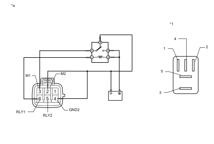
Text in Illustration *1 DEF Relay - - *a Front view of wire harness connector
(to Differential Lock Shift Actuator)
- - -
-
After the free to lock switch is complete, check the limit switch.
Measure the resistance according to the value(s) in the table below.
Standard Resistance Tester Connection Condition Specified Condition 5 (RLY2) - 4 (GND2) After free to lock switch is complete Below 12.5 Ω 6 (RLY1) - 4 (GND2) After free to lock switch is complete 500 kΩ or higher If the result is not as specified, replace the differential lock shift actuator assembly.
-
-
Check the lock to free switch.
-
Connect lines via a relay as shown in the illustration and check that the actuator fork moves from the lock to the free position.
Note
-
Make sure to perform this inspection with the actuator removed from the vehicle. If this inspection is performed with the actuator installed to the vehicle, the actuator will be damaged.
-
When inspecting the actuator, make sure to operate it with the lines connected via a relay. If the lines are not connected via a relay and battery voltage is directly applied to the actuator, the actuator will be damaged.
Tech Tips
When performing the operation described above, use the DEF relay.
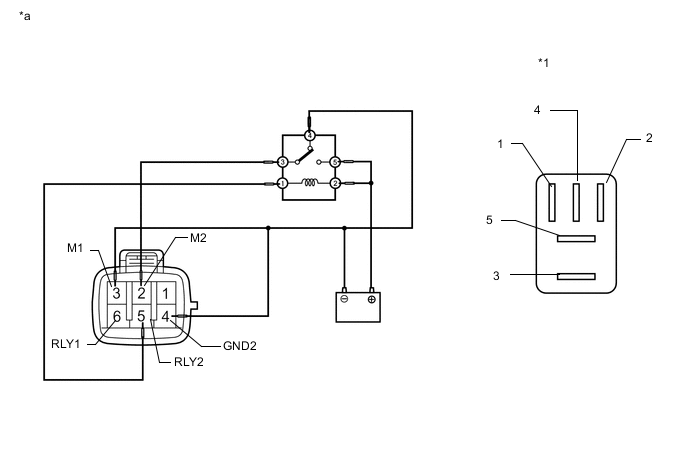
Text in Illustration *1 DEF Relay - - *a Front view of wire harness connector
(to Differential Lock Shift Actuator)
- - -
-
After the lock to free switch is complete, check the limit switch.
Measure the resistance according to the value(s) in the table below.
Standard Resistance Tester Connection Condition Specified Condition 5 (RLY2) - 4 (GND2) After lock to free switch is complete 500 kΩ or higher 6 (RLY1) - 4 (GND2) After lock to free switch is complete Below 12.5 Ω If the result is not as specified, replace the differential lock shift actuator assembly.
-
-