REAR DIFFERENTIAL LOCK ACTUATOR INSTALLATION
PROCEDURE
-
INSTALL DIFFERENTIAL LOCK SHIFT ACTUATOR
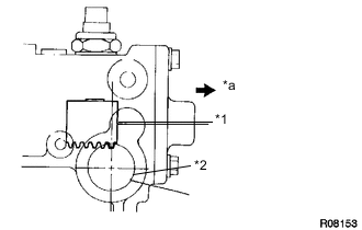
Text in Illustration *1 Shift Fork *2 Actuator Installation Hole *a Outside
-
Check that the outermost rack tooth of the shift fork is approximately above the center line of the actuator installation hole.
-
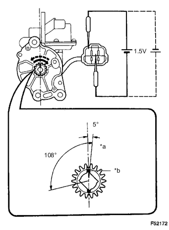
Text in Illustration *a Matchmark *b Groove Make sure that the matchmarks on the pinion of the actuator are in the range of 0 to 5 degrees clockwise from the center line of the actuator.
Note
-
If the matchmarks are not within this range, rotate the pinion.
-
Do not apply positive battery voltage directly to the terminals.
-
If the matchmarks move to the limit of rotation, stop applying electric current.
-
-
Install a new O-ring to the actuator.
-
Apply a light coat of gear oil to the O-ring.
-
Apply MP grease to the gear.
-
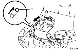
Text in Illustration *a Knock Pin Mack sure that the outermost rack tooth of the shift fork aligns with the matchmarks on the pinion of the actuator.
-
Install the actuator so that the knock pin on the carrier side fits into the long hole on the actuator side.
Tech Tips
Do not damage the O-ring of the actuator.
-
Rotate the actuator counterclockwise so that the knock pin slides to the end of the hole as shown in the illustration.
-
Install the bolts.
- Torque:
- 26.5 N*m { 270 kgf*cm, 20 ft.*lbf }
-
Connect the differential lock actuator connector.
-
Connect the rear differential lock actuator breather hose to the differential actuator assembly.
-
-
ADD DIFFERENTIAL OIL