FRONT PROPELLER SHAFT ASSEMBLY REASSEMBLY

PROCEDURE
-
INSTALL FRONT PROPELLER SHAFT UNIVERSAL JOINT SPIDER BEARING
Tech Tips
Use the same procedure for all propeller shaft universal joint spider bearing.
-
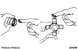
Apply MP grease to a new spider and spider bearing.
Note
Be careful not to apply too much grease.
-
Install the universal joint spider to the propeller shaft.
-
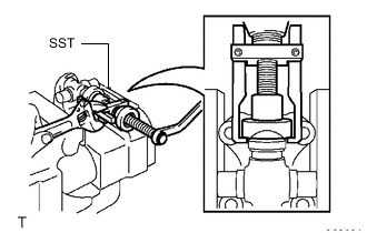
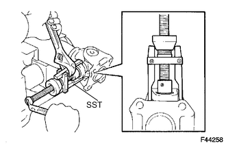
Using SST, install 2 of the spider bearings to the universal joint spider.
- SST
- 09332-25010
-
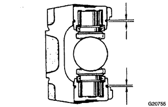
Using SST, adjust both bearings so that the snap ring grooves are at maximum and equal width.
- SST
- 09332-25010
-
Install 4 new snap rings of equal thickness which will allow no axial play.
Tech Tips
Do not reuse the snap rings.
Standard Snap Ring Part No. Mark Specified Condition 90520-25039 1 2.28 to 2.30 mm
(0.0898 to 0.0905 in.)
90520-25040 2 2.30 to 2.32 mm
(0.0906 to 0.0913 in.)
90520-25041 - 2.32 to 2.34 mm
(0.0914 to 0.0921 in.)
90520-25042 Brown 2.34 to 2.36 mm
(0.0922 to 0.0929 in.)
90520-25043 Blue 2.36 to 2.38 mm
(0.0930 to 0.0937 in.)
90520-25044 6 2.38 to 2.40 mm
(0.0938 to 0.0944 in.)
90520-25045 7 2.40 to 2.42 mm
(0.0945 to 0.0952 in.)
90520-25046 8 2.42 to 2.44 mm
(0.0953 to 0.0960 in.)
90520-25047 
2.44 to 2.46 mm
(0.0961 to 0.0968 in.)
90520-25048 10 2.46 to 2.48 mm
(0.0969 to 0.0976 in.)
90520-25049 A 2.48 to 2.50 mm
(0.0977 to 0.0984 in.)
90520-25050 B 2.50 to 2.52 mm
(0.0985 to 0.0992 in.)
90520-25051 C 2.52 to 2.54 mm
(0.0992 to 0.0999 in.)
90520-25052 D 2.54 to 2.56 mm
(0.1000 to 0.1007 in.)
90520-25053 E 2.56 to 2.58 mm
(0.1008 to 0.1015 in.)
90520-25054 J 2.18 to 2.20 mm
(0.0859 to 0.0866 in.)
90520-25055 K 2.20 to 2.22 mm
(0.0867 to 0.0874 in.)
90520-25056 F 2.22 to 2.24 mm
(0.0875 to 0.0881 in.)
90520-25057 G 2.24 to 2.26 mm
(0.0882 to 0.0889 in.)
90520-25058 H 2.26 to 2.28 mm
(0.0890 to 0.0897 in.)
Note
-
Use a new retainer ring.
-
Use retainer rings with as close the same thickness as possible on both ends.
-
-
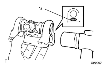
Text in Illustration *a Hammering Point Using a hammer, tap the yoke until there is no clearance between the spider bearing outer race and snap ring.
Tech Tips
Install a new spider bearing on the sleeve side using the procedure described above.
-
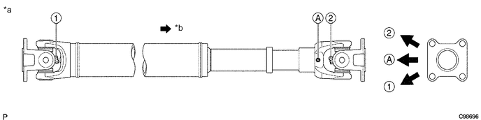
Align the matchmarks on the flange yoke and sleeve yoke.
-
Using SST, install the spider bearings to the universal joint spider.
- SST
- 09332-25010
-
Using SST, adjust both bearings so that the snap ring grooves are at maximum and equal in width.
- SST
- 09332-25010
-
Install 4 new snap rings of equal thickness which will allow 0 mm (0 in.) of axial play.
Tech Tips
Do not reuse the snap rings.
Standard Snap Ring Part No. Mark Specified Condition 90520-25039 1 2.28 to 2.30 mm
(0.0898 to 0.0905 in.)
90520-25040 2 2.30 to 2.32 mm
(0.0906 to 0.0913 in.)
90520-25041 - 2.32 to 2.34 mm
(0.0914 to 0.0921 in.)
90520-25042 Brown 2.34 to 2.36 mm
(0.0922 to 0.0929 in.)
90520-25043 Blue 2.36 to 2.38 mm
(0.0930 to 0.0937 in.)
90520-25044 6 2.38 to 2.40 mm
(0.0938 to 0.0944 in.)
90520-25045 7 2.40 to 2.42 mm
(0.0945 to 0.0952 in.)
90520-25046 8 2.42 to 2.44 mm
(0.0953 to 0.0960 in.)
90520-25047 2.44 to 2.46 mm
(0.0961 to 0.0968 in.)
90520-25048 10 2.46 to 2.48 mm
(0.0969 to 0.0976 in.)
90520-25049 A 2.48 to 2.50 mm
(0.0977 to 0.0984 in.)
90520-25050 B 2.50 to 2.52 mm
(0.0985 to 0.0992 in.)
90520-25051 C 2.52 to 2.54 mm
(0.0992 to 0.0999 in.)
90520-25052 D 2.54 to 2.56 mm
(0.1000 to 0.1007 in.)
90520-25053 E 2.56 to 2.58 mm
(0.1008 to 0.1015 in.)
90520-25054 J 2.18 to 2.20 mm
(0.0859 to 0.0866 in.)
90520-25055 K 2.20 to 2.22 mm
(0.0867 to 0.0874 in.)
90520-25056 F 2.22 to 2.24 mm
(0.0875 to 0.0881 in.)
90520-25057 G 2.24 to 2.26 mm
(0.0882 to 0.0889 in.)
90520-25058 H 2.26 to 2.28 mm
(0.0890 to 0.0897 in.)
Note
-
Use a new retainer ring.
-
Use retainer rings with as close to the same thickness as possible on both ends.
-
-
Text in Illustration *a Hammering Point Using a plastic-faced hammer, tap the yoke until there is no clearance between the spider bearing outer race and snap ring.
Tech Tips
Install a new spider bearing on the sleeve side using the procedure described above.
-
-
INSPECT PROPELLER SHAFT ASSEMBLY
Tech Tips
-
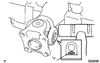
When replacing a spider bearing, be sure that the grease fitting hole is facing the direction shown in the illustration.
-
Fill the grease fittings with MP grease.
Text in Illustration *a Spider Grease Fitting Assembly Direction for Front Propeller Shaft Assembly *b Rear Side -
-
INSPECT FRONT PROPELLER SHAFT UNIVERSAL JOINT SPIDER BEARING