FRONT DRIVE SHAFT ASSEMBLY INSTALLATION

PROCEDURE
-
INSTALL FRONT DRIVE SHAFT ASSEMBLY
-
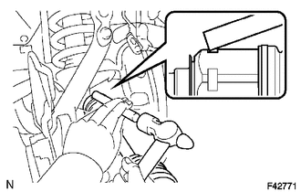
Coat the spline of the inboard joint shaft assembly with ATF.
-
Align the shaft splines and install the drive shaft with a brass bar and hammer.
Note
-
Set the snap ring with the opening side facing downward.
-
Be careful not to damage the oil seal, boot and dust cover.
Tech Tips
Whether the inboard joint shaft is in contact with the pinion shaft or not can be confirmed from the sound or feeling when driving it.
-
-
-
INSTALL FRONT SPEED SENSOR
-
INSTALL LOWER BALL JOINT ATTACHMENT LH
-
Install the lower ball joint attachment with the 2 bolts.
- Torque:
- 160 N*m { 1632 kgf*cm, 118 ft.*lbf }
-
-
CONNECT TIE ROD END SUB-ASSEMBLY LH
-
INSTALL FRONT AXLE SHAFT NUT
-
INSTALL FRONT GREASE HUB CAP
-
FILL UP DIFFERENTIAL OIL
-
INSPECT DIFFERENTIAL OIL
-
INSTALL FRONT WHEEL
- Torque:
- for steel wheel
- 112 N*m { 1137 kgf*cm, 82 ft.*lbf }
- for aluminum wheel
- 103 N*m { 1050 kgf*cm, 76 ft.*lbf }
-
STABILIZE SUSPENSION
-
INSPECT AND ADJUST FRONT WHEEL ALIGNMENT
-
CHECK FRONT SPEED SENSOR SIGNAL
w/o VSC:
w/ VSC (for Hydraulic Brake Booster):
w/ VSC (for Vacuum Brake Booster):