FRONT DRIVE SHAFT ASSEMBLY REASSEMBLY

PROCEDURE
-
INSTALL FRONT DRIVE SHAFT DUST COVER
-
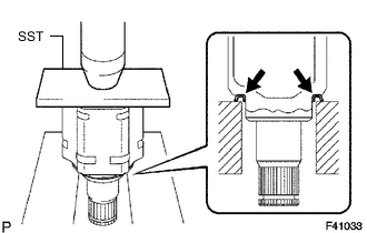
Using SST and a press, install a new dust cover.
- SST
- 09527-10011
-
-
INSTALL SHAFT SNAP RING
-

Install a new snap ring.
-
-
INSTALL OUTBOARD JOINT BOOT
Tech Tips
Before installing the boot, wrap vinyl tape around the spline of the shaft to prevent damage to the boot.
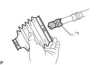
Text in Illustration *1 Vinyl Tape
-
Temporarily install a new outboard joint boot with 2 new clamps to the outboard joint shaft.
-
Pack the outboard joint and boot with grease from the boot kit.
Standard grease capacity 266 to 276 g (9.4 to 9.7 oz.)
-
-
INSTALL FRONT NO. 2 AXLE OUTBOARD JOINT BOOT CLAMP
-
Hold the drive shaft lightly in a vise between aluminum plates.
Note
Do not overtighten the vise.
-
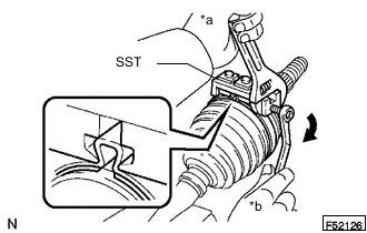
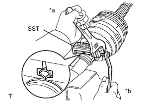
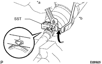
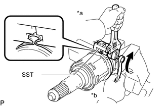
Place SST onto the front No. 2 axle outboard joint boot clamp.
- SST
- 09521-24010
Text in Illustration *a Hold *b Turn -
Tighten SST so that the No. 2 front axle outboard joint boot clamp is pinched.
Note
Do not overtighten SST.
-
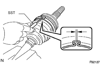
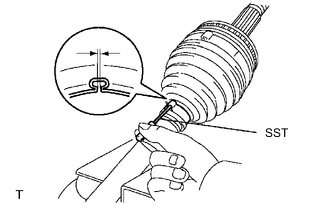
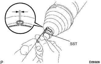
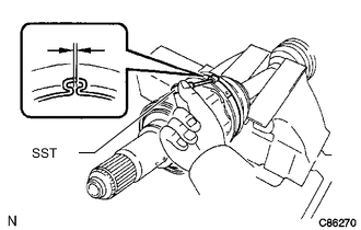
Using SST, measure the clearance of the No. 2 front axle out board joint boot clamp.
- SST
- 09240-00020
Standard clearance 2.1 mm (0.0827 in.) or less Note
If the measured value is more than the specified value, retighten the clamp.
-
-
INSTALL FRONT NO. 1 AXLE OUTBOARD JOINT BOOT CLAMP
-
Hold the drive shaft lightly in a vise between aluminum plates.
Note
Do not overtighten the vise.
-
Secure the outboard joint boot clamp to the boot.
-
Text in Illustration *a Hold *b Turn Place SST onto the outboard joint boot clamp.
- SST
- 09521-24010
-
Tighten SST so that the front axle outboard joint boot clamp is pinched.
Note
Do not overtighten SST.
-
Using SST, measure the clearance of the front axle outboard joint boot clamp.
- SST
- 09240-00020
Standard clearance 1.3 mm (0.0512 in.) or less Note
If the measured value is more than the specified value, retighten the clamp.
-
-
INSTALL INBOARD JOINT BOOT
-
Temporarily install a new inboard joint boot to the outboard joint shaft.
-
-
INSTALL FRONT AXLE INBOARD JOINT ASSEMBLY
-
Install new parts to the outboard joint shaft in the following order.
1. Front axle inboard joint boot clamp 2. Front axle inboard joint boot 3. Front No. 2 axle inboard joint boot clamp -
Secure the outboard joint shaft in a vise between aluminum plates.
Note
Do not overtighten the vise.
-
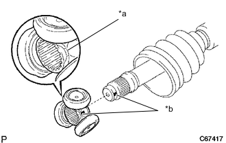
Text in Illustration *a Beveled *b Matchmark Align the matchmarks and install the tripod joint to the outboard joint shaft.
Note
Position tripod so that the beveled side of the tripod faces toward the inboard joint.
-
Align the matchmarks and install the tripod to the inboard joint.
-
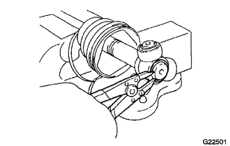
Using a brass bar and hammer, tap the tripod onto the drive shaft.
Note
-
Do not hit the roller portion.
-
Keep the tripod joint free of foreign matter.
-
-
Using a snap ring expander, install a new snap ring.
-
Pack the inboard joint assembly and boot with grease from the boot kit.
Standard grease capacity 239 to 249 g (8.4 to 8.7 oz.) -
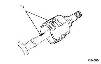
Text in Illustration *a Matchmark Align the matchmarks and install the inboard joint onto the outboard joint shaft.
-
-
INSTALL FRONT NO. 1 AXLE INBOARD JOINT BOOT CLAMP
-
Hold the drive shaft lightly in a vise between aluminum plates.
Note
Do not overtighten the vise.
-
Secure the inboard joint boot clamp to the boot.
-
Text in Illustration *a Hold *b Turn Place SST onto the inboard joint boot clamp.
- SST
- 09521-24010
-
Tighten SST so that the front axle inboard joint boot clamp is pinched.
Note
Do not overtighten SST.
-
Using SST, measure the clearance of the front axle inboard joint boot clamp.
- SST
- 09240-00020
Standard clearance 1.3 mm (0.0512 in.) or less Note
If the measured value is greater than the specified value, retighten the clamp.
-
-
INSTALL FRONT NO. 2 AXLE INBOARD JOINT BOOT CLAMP
-
Hold the inboard joint shaft assembly in a vise between aluminum plates.
Note
Do not overtighten the vise.
-
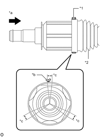
Temporarily install the front No. 2 axle inboard joint boot clamp in the groove of the front axle inboard joint boot.
Tech Tips
When temporarily installing the front No. 2 axle inboard joint boot clamp in the groove of the front axle inboard joint boot, check that the protrusion (staking portion) of the front No. 2 axle inboard joint boot clamp is within one of the 3 ranges shown in the illustration.
-
Text in Illustration *a Front No. 2 Axle Inboard Joint Boot Clamp *b Front Axle Inboard Joint Boot *a Viewpoint *b Protrusion (Staking Portion) *c Installation Range Place SST onto the No. 2 front axle inboard joint boot clamp.
- SST
- 09521-24010
-
Tighten SST so that the No. 2 front axle inboard joint boot clamp is pinched.
Note
Do not overtighten SST.
-
Text in Illustration *a Hold *b Turn Using SST, measure the clearance of the No. 2 front axle inboard joint boot clamp.
- SST
- 09240-00020
Standard clearance 2.1 mm (0.0827 in.) or less Note
If the measured value is greater than the specified value, retighten the clamp.
-