4WD CONTROL SWITCH(w/o Combination Switch) ON-VEHICLE INSPECTION
PROCEDURE
-
INSPECT TRANSFER POSITION SWITCH
-
Check the harness and connector (4 wheel drive control ECU - battery and body ground).
-
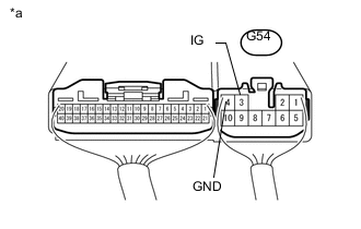
Text in Illustration *a Component with harness connected
(4 wheel drive control ECU)
Measure the voltage according to the value(s) in the table below.
Standard Voltage Tester Connection Switch Condition Specified Condition G54-3 (IG) - Body ground Ignition switch ON 11 to 14 V If the result is not as specified, inspect the harness, fuse or connector. If the harness or connector is malfunctioning, repair or replace the harness or connector. If the harness or connector is normal, replace the 4 wheel drive control ECU Click here.
-
Measure the resistance according to the value(s) in the table below.
Standard Resistance Tester Connection Condition Specified Condition G54-4 (GND) - Body ground Always Below 1 Ω If the result is not as specified, repair or replace the harness or connector.
-
-
Check the harness and connector (transfer position switch - 4 wheel drive control ECU).
-
Disconnect the G53 ECU connector.
-
Disconnect the G18 switch connector.
-
Measure the resistance according to the value(s) in the table below.
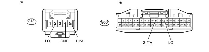
Standard Resistance for 1GR-FE, 1KD-FTV, 1GD-FTV Tester Connection Condition Specified Condition G18-2 (LO) - G53-13 (LO) Always Below 1 Ω G18-2 (LO) - Body ground Always 10 kΩ or higher G18-4 (GND) - Body ground Always Below 1 Ω for 2TR-FE, 5L-E Tester Connection Condition Specified Condition G18-2 (LO) - G53-13 (LO) Always Below 1 Ω G18-2 (LO) - Body ground Always 10 kΩ or higher G18-4 (GND) - Body ground Always Below 1 Ω G18-5 (HI) - G53-11 (2-4) Always Below 1 Ω G18-5 (HI) - Body ground Always 10 kΩ or higher Text in Illustration *A for 2TR-FE, 5L-E - - *a Front view of wire harness connector
(to Transfer Position Switch)
*b Front view of wire harness connector
(to 4 wheel drive control ECU)
If the result is not as specified, repair or replace the harness or connector.
-
-
Check the transfer position switch.
-
Turn the ignition switch off.
-
Connect the G18 switch connector.
-
Connect the G53 ECU connector.
-
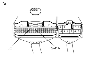
Text in Illustration *A for 2TR-FE, 5L-E *a Component with harness connected
(4 wheel drive control ECU)
Measure the voltage according to the value(s) in the table below.
Standard Voltage for 1GR-FE, 1KD-FTV, 1GD-FTV Tester Connection Switch Condition Specified Condition G53-13 (LO) - Body ground Ignition switch ON
Transfer position switch H4
10.5 to 14 V Ignition switch ON
Transfer position switch L4
Below 1.5 V for 2TR-FE, 5L-E Tester Connection Switch Condition Specified Condition G53-11 (2-4) - Body ground Ignition switch ON
Transfer position switch H4F
Below 1.5 V Ignition switch ON
Transfer position switch H4L
Below 1.5 V Ignition switch ON
Transfer position switch L4L
10.5 to 14 V G53-13 (LO) - Body ground Ignition switch ON
Transfer position switch H4F
10.5 to 14 V Ignition switch ON
Transfer position switch H4L
Below 1.5 V Ignition switch ON
Transfer position switch L4L
Below 1.5 V If the result is not as specified, check the 4 wheel drive control ECU.
-
-
Check the 4 wheel drive control ECU.
-
Disconnect the G18 switch connector.
-
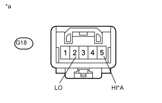
Text in Illustration *A for 2TR-FE, 5L-E *a Front view of wire harness connector
(to Transfer Position Switch)
Measure the voltage according to the value(s) in the table below.
Standard Voltage for 1GR-FE, 1KD-FTV, 1GD-FTV Tester Connection Switch Condition Specified Condition G18-2 (LO) - Body ground Ignition switch ON 10.5 to 14 V for 2TR-FE, 5L-E Tester Connection Switch Condition Specified Condition G18-2 (LO) - Body ground Ignition switch ON 10.5 to 14 V G18-5 (HI) - Body ground Ignition switch ON 10.5 to 14 V If the result is not as specified, replace the 4 wheel drive control ECU Click here.
If the result is normal, replace the transfer position switch Click here.
-
-