4WD CONTROL SWITCH(w/ Combination Switch) INSPECTION
PROCEDURE
-
INSPECT CENTER CLUSTER MODULE SWITCH (TRANSFER POSITION SWITCH)
-
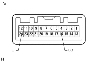
Text in Illustration *a Component without harness connected
(Center Cluster Module Switch (Transfer Position Switch))
Measure the resistance according to the value(s) in the table below.
Standard Resistance Tester Connection Switch Condition Specified Condition 16 (LO) - 24 (E) H4 10 kΩ or higher L4 Below 1 Ω If the result is not as specified, replace the center cluster module switch (transfer position switch).
-
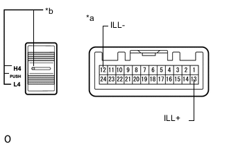
Text in Illustration *a Component without harness connected
(Center Cluster Module Switch (Transfer Position Switch))
*b Center Cluster Module Switch (Transfer Position Switch) Illumination Apply battery voltage between the terminals of the switch, and check the illumination condition of the center cluster module switch (transfer position switch).
Standard Measurement Condition Switch Condition Battery positive (+) → 13 (ILL+) Battery negative (-) → 12 (ILL-) Illuminates If the result is not as specified, replace the center cluster module switch (transfer position switch).
-