TRANSFER SYSTEM 4WD Control Switch Circuit
WIRING DIAGRAM
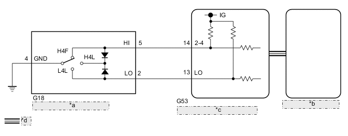
| *a | Transfer Position Switch |
| *b | Combination Meter Assembly |
| *c | 4 Wheel Drive Control ECU |
| *d | CAN Communication Line |
PROCEDURE
-
CHECK 4WD DRIVE MODE
-
Check the 4WD drive mode.
Result Result Proceed to 4 Drive Mode (H4F, H4L, L4F or L4L) (for 1GR-FE, 1GD-FTV or 1KD-FTV ) A 3 Drive Mode (H4F, H4L, or L4L) (for 2TR-FE or 5L-E) B
B 
CONFIRM PROBLEM SYMPTOM Click here
A 
-
-
CONFIRM PROBLEM SYMPTOM
-
Confirm the problem symptoms.
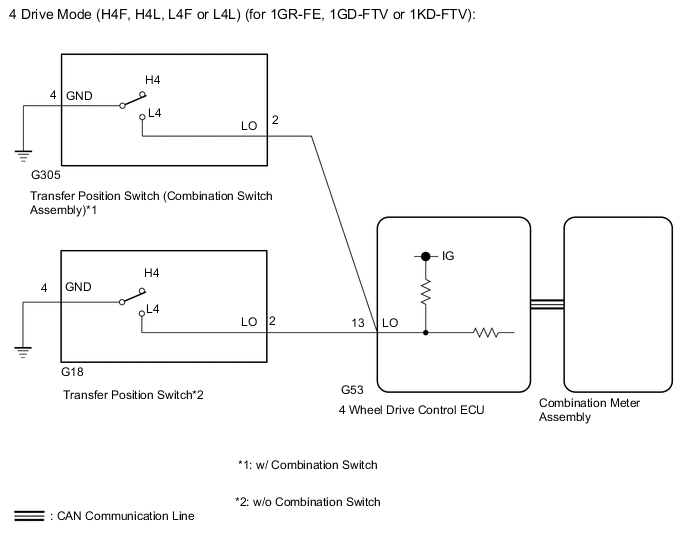
Result Result Proceed to The 4LO indicator light remains off after operating the transfer position switch (combination switch assembly) to L4*1
The 4LO indicator light remains off after operating the transfer position switch to L4*2
A The 4LO indicator light remains on after operating the transfer position switch (combination switch assembly) to H4*1
The 4LO indicator light remains on after operating the transfer position switch to H4*2
B
-
*1: w/ Combination Switch
-
*2: w/o Combination Switch
-
B
CHECK 4LO INDICATOR LIGHT Click here
A
-
-
CHECK 4LO INDICATOR LIGHT
Tech Tips
Perform the following procedure with the vehicle stopped.
-
Turn the ignition switch to ON.
-
for Automatic Transmission:
Move the shift lever to N.
for Manual Transmission:
Depress the clutch pedal.
-
w/ Combination Switch:
Turn the transfer position switch (combination switch assembly) to L4.
w/o Combination Switch:
Turn the transfer position switch to L4.
-
Check the 4LO indicator light.
Result Result Proceed to The 4LO indicator light remains off A The 4LO indicator light is blinking or illuminated B
-
Blinking: Blinks at 0.5 second intervals (0.5 seconds on and 0.5 seconds off)
-
B 
END
A
-
-
CHECK CAN COMMUNICATION LINE
-
Select "Bus Check" from the System Selection Menu screen, and follow the prompts on the screen to inspect the CAN bus.
OK "Bus Check" indicates no malfunctions in CAN communication. Result Result Proceed to DTC is not output A DTC is output B
B
CHECK CAN COMMUNICATION SYSTEM Click here
A
-
-
READ VALUE USING GTS (TRANSFER POSITION SWITCH)
-
Turn the ignition switch off.
-
Connect the GTS to the DLC3.
-
Turn the GTS on.
-
Turn the ignition switch to ON.
-
Enter the following menus: Powertrain / Four Wheel Drive / Data List.
-
According to the display on the GTS, read the Data List.
Four Wheel Drive Tester Display Measurement Item/Range Normal Condition Diagnostic Note Transfer Position Control SW Transfer position switch status/
ON or OFF
ON: L4
OFF: H4
- OK w/ Combination Switch: Display changes according to transfer position switch (combination switch assembly) operation. w/ Combination Switch Display changes according to transfer position switch operation.
NG
INSPECT COMBINATION SWITCH ASSEMBLY OR TRANSFER POSITION SWITCH Click here
OK
-
-
CHECK COMBINATION METER ASSEMBLY (4LO INDICATOR LIGHT)
-
Turn the ignition switch off.
-
Perform an Active Test of the combination meter assembly using the GTS Click here.
-
Check the combination meter assembly.
OK The 4LO indicator light turns on or off in accordance with the GTS.
OK
REPLACE 4 WHEEL DRIVE CONTROL ECU Click here
NG
CHECK METER / GAUGE SYSTEM Click here
-
-
INSPECT COMBINATION SWITCH ASSEMBLY OR TRANSFER POSITION SWITCH
-
w/ Combination Switch:
-
Remove the transfer position switch (combination switch assembly) Click here.
-
Inspect the transfer position switch (combination switch assembly Click here.
OK The transfer position switch (combination switch assembly) operates normally.
-
-
w/o Combination Switch:
-
Remove the transfer position switch Click here.
-
Inspect the transfer position switch Click here.
OK The transfer position switch operates normally.
Result Result Proceed to OK A NG w/ Combination Switch B w/o Combination Switch C -
B
REPLACE COMBINATION SWITCH ASSEMBLY Click here
C
REPLACE TRANSFER POSITION SWITCH Click here
A
-
-
CHECK HARNESS AND CONNECTOR (4 WHEEL DRIVE CONTROL ECU - COMBINATION SWITCH ASSEMBLY OR TRANSFER POSITION SWITCH
-
Disconnect the G53 4 wheel drive control ECU connector.
-
w/ Combination Switch:
Disconnect the G305 transfer position switch (combination switch assembly) connector.
-
w/o Combination Switch:
Disconnect the G18 transfer position switch connector.
-
Measure the resistance according to the value(s) in the table below.
Standard Resistance w/ Combination Switch: Tester Connection Condition Specified Condition G53-13 (LO) - G305-2 (LO) Always Below 1 Ω G53-13 (LO) or G305-2 (LO) - Body ground Always 10 kΩ or higher G305-4 (GND) - Body ground Always Below 1 Ω w/o Combination Switch: Tester Connection Condition Specified Condition G53-13 (LO) - G18-2 (LO) Always Below 1 Ω G53-13 (LO) or G18-2 (LO)) - Body ground Always 10 kΩ or higher G18-4 (GND) - Body ground Always Below 1 Ω
OK
REPLACE 4 WHEEL DRIVE CONTROL ECU Click here
NG
REPAIR OR REPLACE HARNESS OR CONNECTOR
-
-
CHECK 4LO INDICATOR LIGHT
Tech Tips
Perform the following procedure with the vehicle stopped.
-
Turn the ignition switch to ON.
-
for Automatic Transmission:
Move the shift lever to N.
for Manual Transmission:
Depress the clutch pedal.
-
w/ Combination Switch:
Turn the transfer position switch (combination switch assembly) to L4.
w/o Combination Switch:
Turn the transfer position switch to L4.
-
Check the 4LO indicator light.
Result Result Proceed to The 4LO indicator light remains illuminated A The 4LO indicator light is blinking or illuminated B
-
Blinking: Blinks at 0.5 second intervals (0.5 seconds on and 0.5 seconds off)
-
B
END
A
-
-
CHECK CAN COMMUNICATION LINE
-
Select "Bus Check" from the System Selection Menu screen, and follow the prompts on the screen to inspect the CAN bus.
OK "Bus Check" indicates no malfunctions in CAN communication. Result Result Proceed to DTC is not output A DTC is output B
B
CHECK CAN COMMUNICATION SYSTEM Click here
A
-
-
READ VALUE USING GTS (4LO INDICATOR LIGHT)
-
Turn the ignition switch off.
-
Connect the GTS to the DLC3.
-
Turn the GTS on.
-
Turn the ignition switch to ON.
-
Enter the following menus: Powertrain / Four Wheel Drive / Data List.
-
According to the display on the GTS, read the Data List.
Four Wheel Drive Tester Display Measurement Item/Range Normal Condition Diagnostic Note L4 Indicator Request 4LO indicator light request/
Blink3, Blink2*, Blink1, ON, OFF
-
Blink3: Indicator light rapidly blinks
-
Blink1: Indicator light blinks
-
ON: Indicator light illuminates
-
OFF: Indicator light turns off
-
Blinking: 0.5 second intervals (0.5 seconds on and 0.5 seconds off)
-
Rapidly blinking: 0.25 second intervals (0.25 seconds on and 0.25 seconds off)
-
*: Item not equipped, therefore not displayed
-
w/ Combination Switch:
Operate the transfer position switch (combination switch assembly) several times between H4 and L4, and then check the GTS display condition of the 4LO indicator light.
w/o Combination Switch:
Operate the transfer position switch several times between H4 and L4, and then check the GTS display condition of the 4LO indicator light.
Result Result Proceed to Data List continues to display ON even when transfer position switch (combination switch assembly) is operated*1
Data List continues to display ON even when transfer position switch is operated*2
A Data List display changes according to transfer position switch (combination switch assembly) operation*1
Data List display changes according to transfer position switch operation*2
B
-
*1: w/ Combination Switch
-
*2: w/o Combination Switch
-
-
A
REPLACE 4 WHEEL DRIVE CONTROL ECU Click here
B
CHECK METER / GAUGE SYSTEM Click here
-
-
CONFIRM PROBLEM SYMPTOM
-
Confirm the problem symptoms.
Result Result Proceed to The center differential lock indicator light and 4LO indicator light remain off A The center differential lock indicator light remains illuminated, and the 4LO indicator light remains off B The center differential lock indicator light) and 4LO indicator light remain illuminated C
B
CHECK CENTER DIFFERENTIAL LOCK INDICATOR LIGHT Click here
C
CHECK 4LO INDICATOR LIGHT Click here
A
-
-
CHECK CENTER DIFFERENTIAL LOCK INDICATOR LIGHT
-
Turn the ignition switch to ON.
-
for Automatic Transmission:
Move the shift lever to N.
for Manual Transmission:
Depress the clutch pedal.
-
Turn the transfer position switch to H4L.
-
Wait for 60 seconds.
-
Check the center differential lock indicator light.
Result Result Proceed to The center differential lock indicator light blinks*1 or illuminates A The center differential lock indicator light rapidly blinks*2 or remains off B
-
*1 (Blinking): Blinks at 0.5 second intervals (0.5 seconds on and 0.5 seconds off)
-
*2 (Rapidly blinking): Blinks at 0.25 second intervals (0.25 seconds on and 0.25 seconds off)
-
A
END
B
-
-
CHECK DTC
-
Turn the transfer position switch to L4L.
-
Check if DTC P279E is output after 60 seconds elapse (See page ).
Result Result Proceed to DTC P279E is not output A DTC P279E is output B
B
REPAIR CIRCUIT INDICATED BY OUTPUT CODE Click here
A
-
-
CHECK CAN COMMUNICATION LINE
-
Select "Bus Check" from the System Selection Menu screen, and follow the prompts on the screen to inspect the CAN bus.
w/ Central Gateway ECU: Click here
w/o Central Gateway ECU: Click here
OK "Bus Check" indicates no malfunctions in CAN communication. Result Result Proceed to DTC is not output A DTC is output w/ Central Gateway ECU B w/o Central Gateway ECU C
B
CHECK CAN COMMUNICATION SYSTEM Click here
C
CHECK CAN COMMUNICATION SYSTEM Click here
A
-
-
CHECK TRANSFER POSITION SWITCH
-
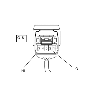
*a Component with harness connected
(Transfer Position Switch)
Remove the transfer position switch with its connector still connected.
-
Measure the voltage according to the value(s) in the table below.
Standard Voltage Tester Connection Switch Condition Specified Condition G18-5 (HI) - Body ground Ignition switch ON
H4F position
Below 1.5 V Ignition switch ON
H4L position
Below 1.5 V Ignition switch ON
L4L position
10.5 to 14 V G18-2 (LO) - Body ground Ignition switch ON
H4F position
10.5 to 14 V Ignition switch ON
H4L position
Below 1.5 V Ignition switch ON
L4L position
Below 1.5 V
OK
CHECK METER / GAUGE SYSTEM Click here
NG
REPLACE TRANSFER POSITION SWITCH Click here
-
-
CHECK CENTER DIFFERENTIAL LOCK INDICATOR LIGHT
-
Turn the ignition switch to ON.
-
for Automatic Transmission:
Move the shift lever to N.
for Manual Transmission:
Depress the clutch pedal.
-
Turn the transfer position switch to H4F.
-
Wait for 60 seconds.
-
Check the center differential lock indicator light.
Result Result Proceed to The center differential lock indicator light blinks*1 or turns off A The center differential lock indicator light rapidly blinks*2 or remains on B
-
*1 (Blinking): Blinks at 0.5 second intervals (0.5 seconds on and 0.5 seconds off)
-
*2 (Rapidly blinking): Blinks at 0.25 second intervals (0.25 seconds on and 0.25 seconds off)
-
A
END
B
GO TO DTC P279E Click here
-
-
CHECK 4LO INDICATOR LIGHT
Tech Tips
Perform the following procedures with the vehicle stopped.
-
Turn the ignition switch to ON.
-
for Automatic Transmission:
Move the shift lever to N.
for Manual Transmission:
Depress the clutch pedal.
-
Turn the transfer position switch to H4L.
-
Wait for 60 seconds.
-
Check the 4LO indicator light.
Result Result Proceed to The 4LO indicator light blinks*1 or turns off A The 4LO indicator light rapidly blinks*2 or remains on B
-
*1 (Blinking): Blinks at 0.5 second intervals (0.5 seconds on and 0.5 seconds off)
-
*2 (Rapidly blinking): Blinks at 0.25 second intervals (0.25 seconds on and 0.25 seconds off)
-
A
END
B
-
-
CHECK DTC
-
Turn the transfer position switch to H4F.
-
Check if DTC P279E is output after 60 seconds elapse.
Result Result Proceed to DTC P279E is not output A DTC P279E is output B
B
REPAIR CIRCUIT INDICATED BY OUTPUT CODE Click here
A
-
-
CHECK TRANSFER POSITION SWITCH
-
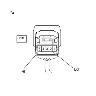
*a Component with harness connected
(Transfer Position Switch)
Remove the transfer position switch with its connector still connected.
-
Measure the voltage according to the value(s) in the table below.
Standard Voltage Tester Connection Switch Condition Specified Condition G18-5 (HI) - Body ground Ignition switch ON
H4F position
Below 1.5 V Ignition switch ON
H4L position
Below 1.5 V Ignition switch ON
L4L position
10.5 to 14 V G18-2 (LO) - Body ground Ignition switch ON
H4F position
10.5 to 14 V Ignition switch ON
H4L position
Below 1.5 V Ignition switch ON
L4L position
Below 1.5 V Result Result Proceed to OK w/ Central Gateway ECU A w/o Central Gateway ECU B NG C
A
CHECK CAN COMMUNICATION SYSTEM Click here
B
CHECK CAN COMMUNICATION SYSTEM Click here
C
REPLACE TRANSFER POSITION SWITCH Click here
-