TRANSFER SYSTEM Clutch Switch Circuit
DESCRIPTION
for 1GR-FE, 1KD-FTV, 1GD-FTV:
While depressing the clutch pedal, the clutch start switch assembly sends a signal to terminal MTN of the 4 wheel drive control ECU. While the signal is input, switching between H4 and L4 is possible.
for 2TR-FE, 5L-E:
While depressing the clutch pedal, the clutch start switch assembly sends a signal to terminal MTN of the 4 wheel drive control ECU. While the signal is input, switching between H4L and L4L is possible.
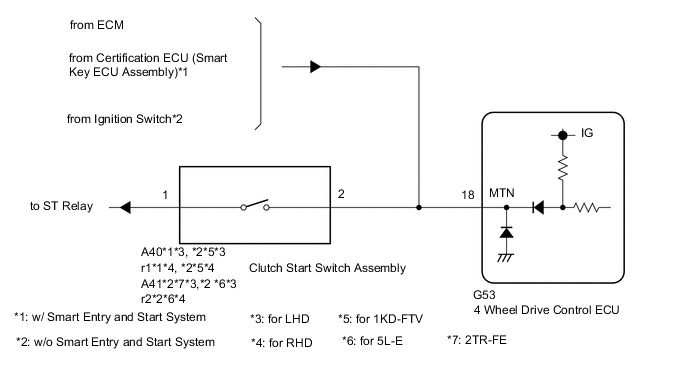
WIRING DIAGRAM
PROCEDURE
-
READ VALUE USING GTS (CLUTCH START SWITCH)
-
Turn the ignition switch off.
-
Connect the GTS to the DLC3.
-
Turn the GTS on.
-
Turn the ignition switch to ON.
-
Enter the following menus: Powertrain / Four Wheel Drive / Data List.
-
According to the display on the GTS, read the Data List.
Four Wheel Drive Tester Display Measurement Item/Range Normal Condition Diagnostic Note Clutch SW Clutch start switch status
ON or OFF
ON: Clutch pedal depressed
OFF: Clutch pedal released
Used only for vehicles with a manual transmission.
Displays OFF for vehicles with an automatic transmission.
OK The display changes according to the clutch pedal operation.
OK 
PROCEED TO NEXT SUSPECTED AREA SHOWN IN PROBLEM SYMPTOMS TABLE Click here
NG 
-
-
CHECK ENGINE CONTROL SYSTEM
-
Check that the engine control system operates normally.
for 1GR-FE: Click here
for 1KD-FTV: Click here
for 1GD-FTV: Click here
for 1GD-FTV (w/Urea SCR System): Click here
for 5L-E: Click here
for 2TR-FE: Click here
OK Engine control system operates normally.
NG
CHECK ENGINE CONTROL SYSTEM for 1GR-FE: Click here
CHECK ENGINE CONTROL SYSTEM for 1KD-FTV: Click here
CHECK ENGINE CONTROL SYSTEM for 1GD-FTV: Click here
CHECK ENGINE CONTROL SYSTEM for 1GD-FTV (w/Urea SCR System): Click here
CHECK ENGINE CONTROL SYSTEM for 5L-E: Click here
CHECK ENGINE CONTROL SYSTEM for 2TR-FE: Click hereOK
-
-
CHECK HARNESS AND CONNECTOR (4 WHEEL DRIVE CONTROL ECU - CLUTCH START SWITCH ASSEMBLY)
-
Disconnect the G53 4 wheel drive control ECU connector.
-
for LHD:
w/ Smart Entry and Start System or w/o Smart Entry and Start System for 1KD-FTV:
Disconnect the A40 clutch start switch assembly connector.
w/o Smart Entry and Start System for 5L-E or w/o Smart Entry and Start System for 2TR-FE:
Disconnect the A41 clutch start switch assembly connector.
-
for RHD:
w/ Smart Entry and Start System or w/o Smart Entry and Start System for 1KD-FTV:
Disconnect the r1 clutch start switch assembly connector.
w/o Smart Entry and Start System for 5L-E:
Disconnect the r2 clutch start switch assembly connector.
-
Measure the resistance according to the value(s) in the table below.
Standard Resistance (for LHD) w/ Smart Entry and Start System or w/o Smart Entry and Start System for 1KD-FTV Tester Connection Condition Specified Condition G53-18 (MTN) - A40-1 Always Below 1 Ω G53-18 (MTN) or A40-1 - Body ground Always 10 kΩ or higher w/o Smart Entry and Start System for 5L-E or w/o Smart Entry and Start System for 2TR-FE Tester Connection Condition Specified Condition G53-18 (MTN) - A41-1 Always Below 1 Ω G53-18 (MTN) or A41-1 - Body ground Always 10 kΩ or higher Standard Resistance (for RHD) w/ Smart Entry and Start System or w/o Smart Entry and Start System for 1KD-FTV Tester Connection Condition Specified Condition G53-18 (MTN) - r1-1 Always Below 1 Ω G53-18 (MTN) or r1-1 - Body ground Always 10 kΩ or higher w/o Smart Entry and Start System for 5L-E Tester Connection Condition Specified Condition G53-18 (MTN) - r2-1 Always Below 1 Ω G53-18 (MTN) or r2-1 - Body ground Always 10 kΩ or higher
OK
REPLACE 4 WHEEL DRIVE CONTROL ECU Click here
NG
REPAIR OR REPLACE HARNESS OR CONNECTOR
-