TRANSFER SYSTEM, Diagnostic DTC:P279E
| DTC Code | DTC Name |
|---|---|
| P279E | Four Wheel Drive (4WD) Range Signal Circuit Range / Performance |
DESCRIPTION
When the transfer position switch is switched, the HI terminal and LO terminal change to one of the following ON/OFF combinations listed in the table below.
| Transfer Position Switch Terminal | H4F | Between H4F and H4L | H4L | Between H4L and L4L | L4L |
|---|---|---|---|---|---|
| HI | ON | OFF | ON | OFF | OFF |
| LO | OFF | OFF | ON | OFF | ON |
This DTC is detected if the transfer position switch HI terminal and LO terminal signals are simultaneously received.
| DTC No. | DTC Detection Condition
|
Trouble Area |
|---|---|---|
| P163B |
|
|
WIRING DIAGRAM
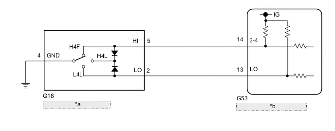
| *a | Transfer Position Switch |
| *b | 4 Wheel Drive Control ECU |
PROCEDURE
-
CHECK HARNESS AND CONNECTOR (4 WHEEL DRIVE CONTROL ECU - TRANSFER POSITION SWITCH)
-
Disconnect the G53 4 wheel drive control ECU connector.
-
Disconnect the G18 transfer position switch connector.
-
Measure the resistance according to the value(s) in the table below.
Standard Resistance Tester Connection Condition Specified Condition G53-14 (2-4) - G18-5 (HI) Always Below 1 Ω G53-13 (LO) - G18-2 (LO) Always Below 1 Ω G18-4 (GND) - Body ground Always Below 1 Ω G53-14 (2-4) or G18-5 (HI) - Body ground Always 10 kΩ or higher G53-13 (LO) or G18-2 (LO) - Body ground Always 10 kΩ or higher G53-14 (2-4) or G18-5 (HI) - G53-13 (LO) or G18-2 (LO) Always 10 kΩ or higher Result Proceed to OK NG
NG 
REPAIR OR REPLACE HARNESS OR CONNECTOR
OK 
-
-
CHECK TRANSFER POSITION SWITCH
-
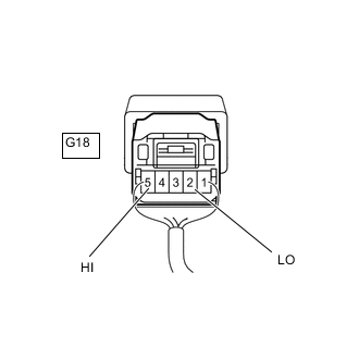
*a Component with harness connected
(Transfer Position Switch)
Remove the transfer position switch with its connector still connected.
-
Measure the voltage according to the value(s) in the table below.
Standard Voltage Tester Connection Switch Condition Specified Condition G18-5 (HI) - Body ground Ignition switch ON
H4F position
Below 1.5 V Ignition switch ON
H4L position
Below 1.5 V Ignition switch ON
L4L position
10.5 to 14 V G18-2 (LO) - Body ground Ignition switch ON
H4F position
10.5 to 14 V Ignition switch ON
H4L position
Below 1.5 V Ignition switch ON
L4L position
Below 1.5 V Result Proceed to OK NG
OK
REPLACE 4 WHEEL DRIVE CONTROL ECU Click here
NG
REPLACE TRANSFER POSITION SWITCH Click here
-