TRANSFER SYSTEM TERMINALS OF ECU
-
CHECK 4 WHEEL DRIVE CONTROL ECU
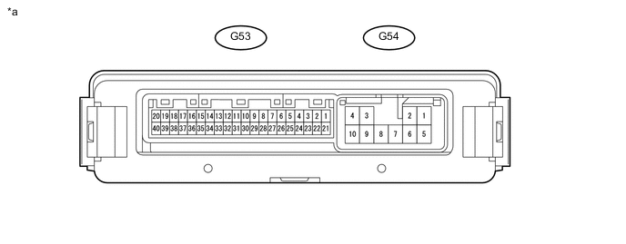
*a Component with harness connected
(4 Wheel Drive Control ECU)
- -
-
Measure the voltage and resistance according to the value(s) in the table below.
3 Drive Mode (H4F, H4L, or L4L) (for 2TR-FE or 5L-E) Terminal No. (Symbol) Wiring Color Terminal Description Condition Specified Condition G53-3 (P1) - G54-10 (GND) W - W-B Center differential lock detection switch input Ignition switch ON
Center differential free
9.5 to 14 V Ignition switch ON
Center differential lock
Below 1.5 V G53-7 (HL2) - G54-10 (GND) LG - W-B High-low transfer limit switch input Ignition switch ON
Shift lever in neutral*1
Shift lever in N*2
Transfer high
Below 1.5 V Ignition switch ON
Shift lever in neutral*1
Shift lever in N*2
Switching between transfer high and low
Below 1.5 V ←→ 10.5 to 14 V Ignition switch ON
Shift lever in neutral*1
Shift lever in N*2
Transfer low
10.5 to 14 V G53-8 (HL1) - G54-10 (GND) GR - W-B High-low transfer limit switch input Ignition switch ON
Shift lever in neutral*1
Shift lever in N*2
Transfer high
10.5 to 14 V Ignition switch ON
Shift lever in neutral*1
Shift lever in N*2
Switching between transfer high and low
10.5 to 14 V ←→ Below 1.5 V Ignition switch ON
Shift lever in neutral*1
Shift lever in N*2
Transfer low
Below 1.5 V G53-9 (TL3) - G54-10 (GND) G - W-B Center differential lock limit switch input Ignition switch ON
Center differential free
Below 1.5 V Ignition switch ON
Switching center differential between free and lock
Below 1.5 V Ignition switch ON
Center differential lock
10.5 to 14 V G53-10 (TL2) - G54-10 (GND) V - W-B Center differential lock limit switch input Ignition switch ON
Center differential free
10.5 to 14 V Ignition switch ON
Switching center differential between free and lock
Below 1.5 V Ignition switch ON
Center differential lock
Below 1.5 V G53-13 (LO) - G54-10 (GND) GR - W-B Transfer position switch input Ignition switch ON
Transfer position switch H4F
10.5 to 14 V Ignition switch ON
Transfer position switch H4L
Below 1.5 V Ignition switch ON
Transfer position switch L4L
Below 1.5 V G53-14 (2-4) - G54-10 (GND) P - W-B Transfer position switch input Ignition switch ON
Transfer position switch H4F
Below 1.5 V Ignition switch ON
Transfer position switch H4L
Below 1.5 V Ignition switch ON
Transfer position switch L4L
10.5 to 14 V G53-16 (L4) - G54-10 (GND) R - W-B L4 output signal Ignition switch ON
Transfer high
10 to 14 V Ignition switch ON
Transfer low
Below 1.5 V G53-18 (MTN) - G54-10 (GND)*1 B - W-B Clutch start switch input Ignition switch ON
Clutch pedal released
9.5 to 14 V Ignition switch ON
Clutch pedal depressed
Below 1.5 V G53-20 (CANH) - G53-40 (CANL) G - W CAN communication line Ignition switch off
Cable disconnected from negative (-) battery terminal
54 to 69 Ω G53-21 (+B) - G54-10 (GND) W - W-B ECU power supply Always 11 to 14 V G54-2 (HM1) - G54-10 (GND) B - W-B High-low transfer shift motor output Ignition switch ON
Clutch pedal depressed*1
Shift lever in N*2
Transfer position switch switched from H4L to L4L
(Switching from transfer high to low)
Below 1.5 V Ignition switch ON
Clutch pedal depressed*1
Shift lever in N*2
Transfer position switch switched from L4L to H4L
(Switching from transfer low to high)
10 to 14 V G54-4 (IG) - G54-10 (GND) R - W-B ECU and actuator power supply Ignition switch ON 11 to 14 V G54-6 (HM2) - G54-10 (GND) W - W-B High-low transfer shift motor output Ignition switch ON
Clutch pedal depressed*1
Shift lever in N*2
Transfer position switch switched from H4L to L4L
(Switching from transfer high to low)
10 to 14 V Ignition switch ON
Clutch pedal depressed*1
Shift lever in N*2
Transfer position switch switched from L4L to H4L
(Switching from transfer low to high)
Below 1.5 V G54-7 (TM2) - G54-10 (GND) V - W-B Center differential lock shift motor output Ignition switch ON
Transfer position switch switched from H4F to H4L
(Switching center differential from free to lock)
Below 1.5 V Ignition switch ON
Transfer position switch switched from H4L to H4F
(Switching center differential from lock to free)
10 to 14 V G54-8 (TM1) - G54-10 (GND) P - W-B Center differential lock shift motor output Ignition switch ON
Transfer position switch switched from H4F to H4L
(Switching center differential from free to lock)
10 to 14 V Ignition switch ON
Transfer position switch switched from H4L to H4F
(Switching center differential from lock to free)
Below 1.5 V G54-10 (GND) - Body ground W-B - Body ground GND Always Below 1 Ω
-
*1: for Manual Transmission
-
*2: for Automatic Transmission
4 Drive Mode (H4F, H4L, L4F or L4L) (for 1GR-FE, 1GD-FTV or 1KD-FTV) Terminal No. (Symbol) Wiring Color Terminal Description Condition Specified Condition G53-3 (P1) - G54-10 (GND) W - W-B Center differential lock detection switch input Ignition switch ON
Center differential free
9.5 to 14 V Ignition switch ON
Center differential lock
Below 1.5 V G53-6 (DL) - G54-10 (GND) W - W-B Center differential lock switch input Ignition switch ON
Center differential lock switch not pressed
9.5 to 14 V Ignition switch ON
Center differential lock switch pressed and held
Below 1.5 V G53-7 (HL2) - G54-10 (GND) LG - W-B High-low transfer limit switch input Ignition switch ON
Shift lever in neutral*1
Shift lever in N*2
Transfer high
When transfer is in neutral*1
Below 1.5 V Ignition switch ON
Shift lever in neutral*1
Shift lever in N*2
Switching between transfer high and low
Below 1.5 V ←→ 10.5 to 14 V Ignition switch ON
Shift lever in neutral*1
Shift lever in N*2
Transfer low
10.5 to 14 V G53-8 (HL1) - G54-10 (GND) GR - W-B High-low transfer limit switch input Ignition switch ON
Shift lever in neutral*1
Shift lever in N*2
Transfer high
10.5 to 14 V Ignition switch ON
Shift lever in neutral*1
Shift lever in N*2
Switching between transfer high and low
10.5 to 14 V ←→ Below 1.5 V Ignition switch ON
Shift lever in neutral*1
Shift lever in N*2
Transfer low
Below 1.5 V G53-9 (TL3) - G54-10 (GND) G - W-B Center differential lock limit switch input Ignition switch ON
Center differential free
Below 1.5 V Ignition switch ON
Switching center differential between free and lock
Below 1.5 V Ignition switch ON
Center differential lock
10.5 to 14 V G53-10 (TL2) - G54-10 (GND) V - W-B Center differential lock limit switch input Ignition switch ON
Center differential free
10.5 to 14 V Ignition switch ON
Switching center differential between free and lock
Below 1.5 V Ignition switch ON
Center differential lock
Below 1.5 V G53-13 (LO) - G54-10 (GND) GR - W-B Transfer position switch input Ignition switch ON
Transfer position switch H4
10 to 14 V Ignition switch ON
Transfer position switch L4
Below 1.5 V G53-16 (L4) - G54-10 (GND) R - W-B L4 output signal Ignition switch ON
Transfer high
10 to 14 V Ignition switch ON
Transfer low
Below 1.5 V G53-18 (MTN) - G54-10 (GND)*1 B - W-B Clutch start switch input Ignition switch ON
Clutch pedal released
9.5 to 14 V Ignition switch ON
Clutch pedal depressed
Below 1.5 V G53-20 (CANH) - G53-40 (CANL) G - W CAN communication line Ignition switch off
Cable disconnected from negative (-) battery terminal
54 to 69 Ω G53-21 (+B) - G54-10 (GND) W - W-B ECU power supply Always 11 to 14 V G54-2 (HM1) - G54-10 (GND) B - W-B High-low transfer shift motor output Ignition switch ON
Clutch pedal depressed*1
Shift lever in N*2
Transfer position switch switched from H4 to L4
(Switching from transfer high to low)
Below 1.5 V Ignition switch ON
Clutch pedal depressed*1
Shift lever in N*2
Transfer position switch switched from L4 to H4
(Switching from transfer low to high)
10 to 14 V G54-4 (IG) - G54-10 (GND) R - W-B ECU and actuator power supply Ignition switch ON 11 to 14 V G54-6 (HM2) - G54-10 (GND) W - W-B High-low transfer shift motor output Ignition switch ON
Clutch pedal depressed*1
Shift lever in N*2
Transfer position switch switched from H4 to L4
(Switching from transfer high to low)
10 to 14 V Ignition switch ON
Clutch pedal depressed*1
Shift lever in N*2
Transfer position switch switched from L4 to H4
(Switching from transfer low to high)
Below 1.5 V G54-7 (TM2) - G54-10 (GND) V - W-B Center differential lock shift motor output Ignition switch ON
Center differential lock switch pressed to switch from free to lock
(Switching center differential from free to lock)
Below 1.5 V Ignition switch ON
Center differential lock switch pressed to switch from lock to free
(Switching center differential from lock to free)
10 to 14 V G54-8 (TM1) - G54-10 (GND) P - W-B Center differential lock shift motor output Ignition switch ON
Center differential lock switch pressed to switch from free to lock
(Switching center differential from free to lock)
10 to 14 V Ignition switch ON
Center differential lock switch pressed to switch from lock to free
(Switching center differential from lock to free)
Below 1.5 V G54-10 (GND) - Body ground W-B - Body ground GND Always Below 1 Ω
-
*1: for Manual Transmission
-
*2: for Automatic Transmission
-
-