TRANSFER ASSEMBLY INSPECTION

PROCEDURE
-
INSPECT TRANSFER INPUT SHAFT
-
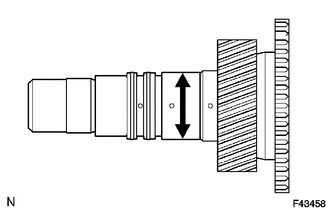
Using a micrometer, measure the outer diameter of the input shaft journal surface.
Minimum diameter 47.59 mm (1.88 in.) If the outer diameter is less than the minimum, replace the input shaft.
-
-
INSPECT PLANETARY PINION GEAR THRUST CLEARANCE
-
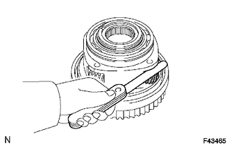
Using a feeler gauge, measure the thrust clearance of the planetary pinion gear.
Standard clearance 0.11 to 0.84 mm (0.00434 to 0.0330 in.) Maximum clearance 0.84 mm (0.0330 in.) If the clearance is more than the maximum, replace the planetary gear.
-
-
INSPECT PLANETARY PINION GEAR RADIAL CLEARANCE
-
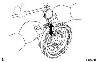
Using a dial indicator, measure the radial clearance of the planetary pinion gear.
Standard clearance 0.009 to 0.038 mm (0.000355 to 0.00149 in.) Maximum clearance 0.038 mm (0.00149 in.) If the clearance is more than the maximum, replace the planetary gear.
-
-
INSPECT TRANSFER OUTPUT SHAFT REAR
-
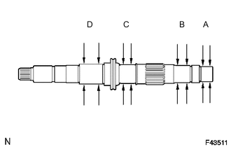
Using a micrometer, measure the outer diameter of the output shaft rear journal surfaces.
Standard diameter Journal A 27.98 to 27.99 mm (1.1015 to 1.1019 in.) Journal B 31.98 to 32.00 mm (1.2591 to 1.2598 in.) Journal C 34.98 to 35.00 mm (1.3772 to 1.3779 in.) Journal D 36.98 to 37.00 mm (1.4560 to 1.4566 in.) Minimum diameter Journal A 27.98 mm (1.1015 in.) Journal B 31.98 mm (1.2591 in.) Journal C 34.98 mm (1.3772 in.) Journal D 36.98 mm (1.4560 in.) If the outer diameter is less than the minimum, replace the rear output shaft.
-
-
INSPECT TRANSFER HIGH AND LOW CLUTCH SLEEVE AND NO. 2 TRANSFER GEAR SHIFT FORK CLEARANCE
-
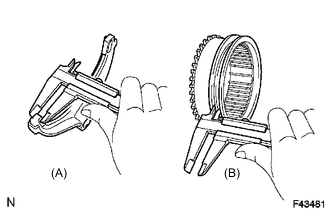
Using a vernier caliper, measure the thickness of the shift fork claw.
Standard thickness (A) 10 mm (0.394 in.) -
Using a vernier caliper, measure the width of the groove of the high and low clutch sleeve.
Standard width (B) 10.5 mm (0.413 in.) -
Calculate the clearance between the high and low clutch sleeve and shift fork.
Standard clearance (B) - (A) 0.26 to 0.84 mm (0.0103 to 0.0330 in.) Maximum clearance (B) - (A) 0.84 mm (0.0330 in.) If the clearance is more than the maximum, replace the high and low clutch sleeve or shift fork.
-
-
INSPECT FRONT DRIVE CLUTCH SLEEVE AND CENTER DIFFERENTIAL LOCK FORK SUB-ASSEMBLY CLEARANCE
-
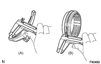
Using a vernier caliper, measure the thickness of the center differential lock fork claw.
Standard thickness (A) 10 mm (0.394 in.) -
Using a vernier caliper, measure the width of the groove of the front drive clutch sleeve.
Standard width (B) 10.5 mm (0.413 in.) -
Calculate the clearance between the front drive clutch sleeve and differential lock fork.
Standard clearance (B) - (A) 0.26 to 0.84 mm (0.0103 to 0.0330 in.) Maximum clearance (B) - (A) 0.84 mm (0.0330 in.) If the clearance is more than the maximum, replace the front drive clutch sleeve or differential lock fork.
-
-
INSPECT CENTER DIFFERENTIAL CASE AND TRANSFER HIGH AND LOW CLUTCH SLEEVE
-
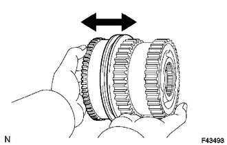
Check that the splines of the clutch sleeve are not worn.
-
Install the clutch sleeve to the center differential case and check that the clutch sleeve moves smoothly.
-
-
INSPECT CENTER DIFFERENTIAL CASE AND FRONT DRIVE CLUTCH SLEEVE
-
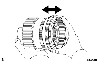
Check that the splines of the clutch sleeve are not worn.
-
Install the clutch sleeve to the center differential case and check that the clutch sleeve moves smoothly.
-
-
INSPECT TRANSFER SHIFT ACTUATOR ASSEMBLY
-
Inspect the multi mode transfer shift actuator (transfer shift actuator assembly).
-
Remove the transfer shift actuator assembly
-
Check the LOCK to FREE switch.
Connect lines via a relay as shown in the illustration, then check that the actuator fork moves from the LOCK to FREE position.
Note
-
Perform this inspection with the actuator removed from the vehicle. If this inspection is performed with the actuator installed to the vehicle, the actuator will be damaged.
-
When inspecting the actuator, operate it with the lines connected via a relay. If the lines are not connected via a relay and battery voltage is directly applied to the actuator, the actuator will be damaged.
Tech Tips
When performing the operation described above, use the DEF relay on the main body ECU (instrument panel junction block).
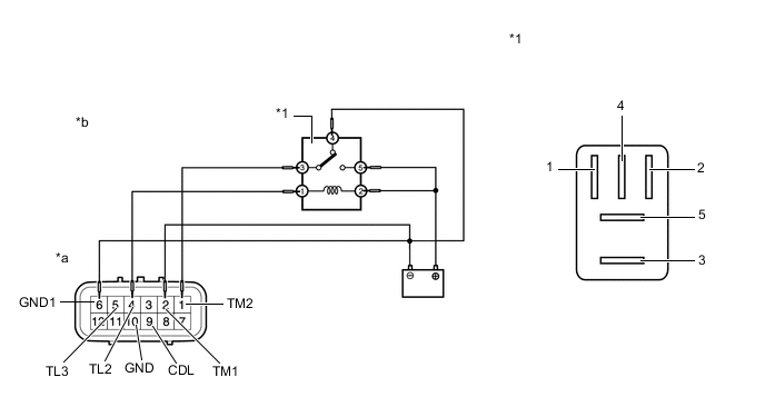
*1 DEF Relay - - *a Component without harness connected
(Transfer Shift Actuator Assembly)
*b LOCK to FREE
-
After the LOCK to FREE switch is complete, inspect the center differential lock detection switch and limit switch.
Standard Resistance Tester Connection Condition Specified Condition 4 (TL2) - 6 (GND1) After LOCK to FREE switch is complete 0.5 MΩ or higher 5 (TL3) - 6 (GND1) After LOCK to FREE switch is complete Below 12.5 Ω 9 (CDL) - 10 (GND) After LOCK to FREE switch is complete 0.5 MΩ or higher
-
-
Check the FREE to LOCK switch.
Connect lines via a relay as shown in the illustration, then check that the actuator fork moves from the FREE to LOCK position.
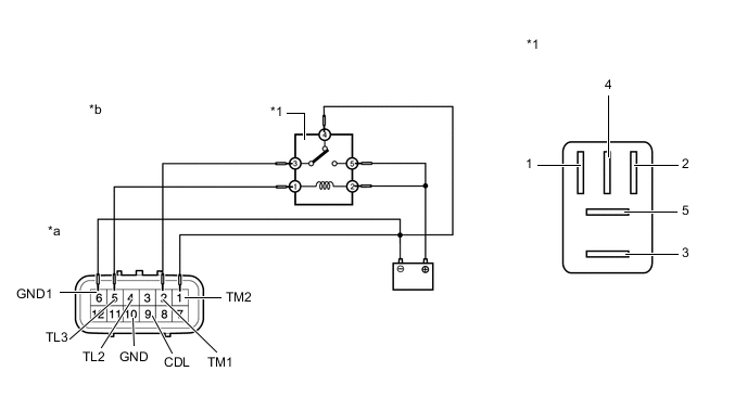
*1 DEF Relay - - *a Component without harness connected
(Transfer Shift Actuator Assembly)
*b FREE to LOCK
-
After the FREE to LOCK switch is complete, inspect the center differential lock detection switch and limit switch.
Standard Resistance Tester Connection Condition Specified Condition 4 (TL2) - 6 (GND1) After FREE to LOCK switch is complete Below 12.5 Ω 5 (TL3) - 6 (GND1) After FREE to LOCK switch is complete 0.5 MΩ or higher 9 (CDL) - 10 (GND) After FREE to LOCK switch is complete Below 12.5 Ω If the result is not as specified, replace the transfer shift actuator assembly Click here
If the transfer shift actuator assembly is normal, replace the 4 wheel drive control ECU Click here
-
-
-
Inspect the high-low transfer shift actuator (transfer shift actuator assembly).
-
Remove the transfer shift actuator assembly
-
Check the HIGH to LOW switch.
Connect lines via a relay as shown in the illustration, then check that the actuator fork moves from the HIGH to LOW position.
Note
-
Perform this inspection with the actuator removed from the vehicle. If this inspection is performed with the actuator installed to the vehicle, the actuator will be damaged.
-
When inspecting the actuator, operate it with the lines connected via a relay. If the lines are not connected via a relay and battery voltage is directly applied to the actuator, the actuator will be damaged.
Tech Tips
When performing the operation described above, use the DEF relay on the main body ECU (instrument panel junction block).
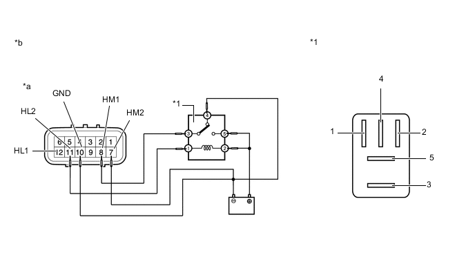
*1 DEF Relay - - *a Component without harness connected
(Transfer Shift Actuator Assembly)
*b HIGH to LOW
-
After the HIGH to LOW switch is complete, inspect the limit switch.
Standard Resistance Tester Connection Condition Specified Condition 12 (HL1) - 10 (GND) After HIGH to LOW switch is complete Below 12.5 Ω 11 (HL2) - 10 (GND) After HIGH to LOW switch is complete 0.5 MΩ or higher
-
-
Check the HIGH to LOW switch.
Connect lines via a relay as shown in the illustration, then check that the actuator fork moves from the HIGH to LOW position.
Note
-
Perform this inspection with the actuator removed from the vehicle. If this inspection is performed with the actuator installed to the vehicle, the actuator will be damaged.
-
When inspecting the actuator, operate it with the lines connected via a relay. If the lines are not connected via a relay and battery voltage is directly applied to the actuator, the actuator will be damaged.
Tech Tips
When performing the operation described above, use the DEF relay on the main body ECU (instrument panel junction block).

*1 DEF Relay - - *a Component without harness connected
(Transfer Shift Actuator Assembly)
*b HIGH to LOW
-
After the HIGH to LOW switch is complete, inspect the limit switch.
Standard Resistance Tester Connection Condition Specified Condition 12 (HL1) - 10 (GND) After HIGH to LOW switch is complete Below 12.5 Ω 11 (HL2) - 10 (GND) After HIGH to LOW switch is complete 0.5 MΩ or higher If the result is not as specified, replace the transfer shift actuator assembly Click here
If the transfer shift actuator assembly is normal, replace the 4 wheel drive control ECU Click here
-
-
-