OUTPUT SHAFT INSPECTION

PROCEDURE
-
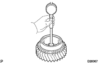
INSPECT OUTPUT SHAFT
-
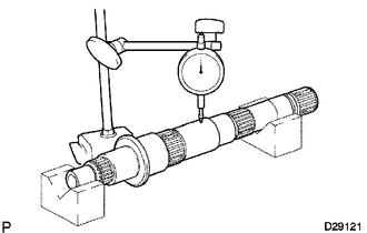
Using a dial indicator, measure the output shaft runout.
Maximum runout 0.03 mm (0.00118 in.)
-
If the runout is more than the maximum, replace the output shaft with a new one.
-
-
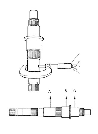
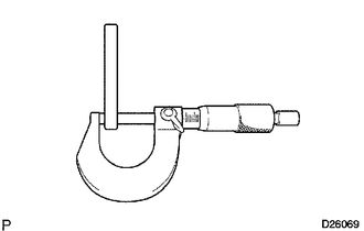
Using a micrometer, measure the journal diameter at A, B and C on the output shaft.
Standard Journal Diameter Item Specified Condition Journal A 38.979 to 38.995 mm (1.5346 to 1.5352 in.) Journal B 46.984 to 47.000 mm (1.8498 to 1.8504 in.) Journal C 37.984 to 38.000 mm (1.4954 to 1.4961 in.)
-
If the diameter is not as specified, replace the output shaft with a new one.
-
-
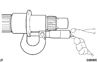
Using a micrometer, measure the thickness of the output shaft flange as shown in the illustration.
Standard thickness 4.8 to 5.2 mm (0.189 to 0.204 in.)
-
If the thickness is not as specified, replace the output shaft.
-
-
-
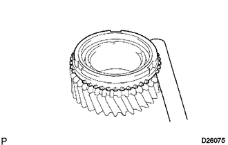
INSPECT 3RD GEAR
-
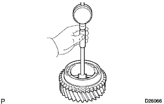
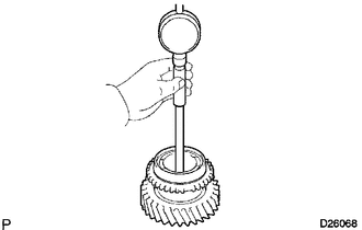
Using a cylinder gauge, measure the inside diameter of the 3rd gear.
Standard inside diameter 44.015 to 44.040 mm (1.7329 to 1.7339 in.) Maximum inside diameter 44.040 mm (1.7339 in.)
-
If the inside diameter is more than the maximum, replace the 3rd gear with a new one.
-
-
-
INSPECT 2ND GEAR
-
Using a cylinder gauge, measure the inside diameter of the 2nd gear.
Standard inside diameter 53.015 to 53.040 mm (2.0872 to 2.0881 in.) Maximum inside diameter 53.040 mm (2.0881 in.)
-
If the inside diameter is more than the maximum, replace the 2nd gear with a new one.
-
-
-
INSPECT 1ST GEAR
-
Using a cylinder gauge, measure the inside diameter of the 1st gear.
Standard inside diameter 46.015 to 46.040 mm (1.812 to 1.8126 in.) Maximum inside diameter 46.040 mm (1.8126 in.)
-
If the inside diameter is more than the maximum, replace the 1st gear with a new one.
-
-
-
INSPECT 1ST GEAR THRUST WASHER
-
Using a micrometer, measure the thickness of the thrust washer.
Standard thickness 5.95 to 6.05 mm (0.235 to 0.238 in.) Minimum thickness 5.95 mm (0.235 in.)
-
If the thickness is less than the minimum, replace the 1st gear thrust washer.
-
-
-
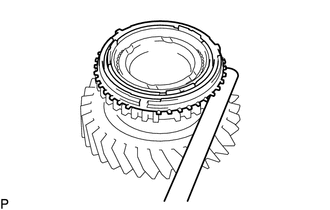
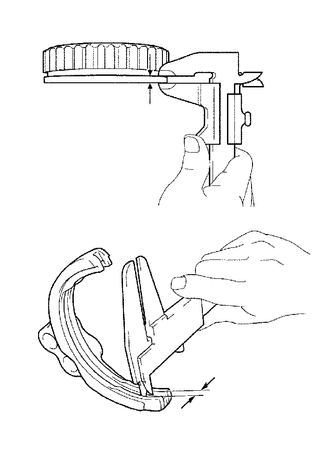
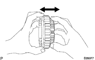
INSPECT NO. 1 SYNCHRONIZER RING SET (for 1st Gear)
-
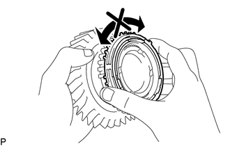
Apply gear oil to the cone of the 1st gear, and check that the No. 1 synchronizer ring set does not turn in either direction while pushing the No. 1 synchronizer ring set.
-
If No. 1 synchronizer ring set turns, replace it.
-
-
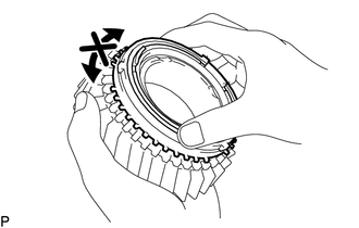
Measure the clearance between the No. 1 synchronizer ring and 1st gear while pushing the No. 1 synchronizer ring against the cone of the 1st gear.
Standard clearance 0.75 to 1.65 mm (0.0295 to 0.0650 in.)
-
If the clearance is not as specified, replace the No. 1 synchronizer ring with a new one.
-
-
-
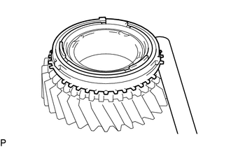
INSPECT NO. 1 SYNCHRONIZER RING SET (for 2nd Gear)
-
Apply gear oil to the cone of the 2nd gear, and check that No. 1 synchronizer ring set does not turn in either direction while pushing the No. 1 synchronizer ring set.
-
If No. 1 synchronizer ring set turns, replace it.
-
-
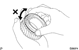
Push the No. 1 synchronizer ring set against the cone of the 2nd gear. Measure the clearance between the No. 1 synchronizer ring set and 2nd gear.
Standard clearance 0.65 to 1.75 mm (0.0256 to 0.0689 in.)
-
If the clearance is not as specified, replace the No. 1 synchronizer ring with a new one.
-
-
-
INSPECT NO. 2 SYNCHRONIZER RING (for 3rd Gear)
-
Apply gear oil to the cone of the 3rd gear, and check that No. 2 synchronizer ring does not turn in either direction while pushing the No. 2 synchronizer ring.
-
If the No. 2 synchronizer ring turns, replace it.
-
-
Push the No. 2 synchronizer ring against the cone of the 3rd gear. Measure the clearance between the No. 2 synchronizer ring (for the 3rd gear) and 3rd gear.
Standard clearance 0.75 to 1.65 mm (0.0295 to 0.0650 in.)
-
If the clearance is not as specified, replace the No. 2 synchronizer ring with a new one.
-
-
-
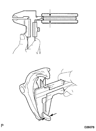
INSPECT REVERSE GEAR
-
Using a vernier caliper, measure the groove of the No. 1 shift fork and the thickness of flange of the reverse gear. Then calculate the clearance between the No. 1 shift fork and flange.
Standard clearance 0.15 to 0.41 mm (0.00591 to 0.0161 in.)
-
If the clearance is not as specified, replace the reverse gear and No. 1 shift fork with new ones.
-
-
-
INSPECT NO. 1 TRANSMISSION CLUTCH HUB
-
Check the sliding condition between the No. 1 clutch hub and reverse gear.
-
Check the spline of the reverse gear for wear.
-
If there are any defects, replace the No. 1 clutch hub.
-
-
-
INSPECT NO. 2 TRANSMISSION HUB SLEEVE
-
Using a vernier caliper, measure the groove of the No. 2 hub sleeve and the thickness of claw of the No. 2 shift fork. Then calculate the clearance between the No. 2 hub sleeve and the claw.
Standard clearance 0.15 to 0.35 mm (0.00591 to 0.0138 in.)
-
If the clearance is not as specified, replace the No. 2 hub sleeve and No. 2 shift fork with new ones.
-
-
-
INSPECT TRANSMISSION CLUTCH HUB NO. 2
-

Check the sliding condition between the No. 2 clutch hub and No. 2 hub sleeve.
-
Check the splines of the No. 1 clutch hub for wear.
-
Check the tip of the spline gear sleeve of the reverse gear for wear.
-
If there are any defects, replace the No. 1 clutch hub or reverse gear.
-
-