OUTPUT SHAFT DISASSEMBLY

PROCEDURE
-
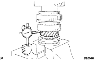
INSPECT 1ST GEAR THRUST CLEARANCE
-
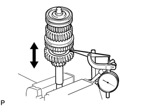
Using a dial indicator, measure the thrust clearance.
Standard clearance 0.20 to 0.45 mm (0.00787 to 0.0177 in.)
-
If the clearance is not as specified, replace the No. 1 synchronizer ring set.
-
-
-
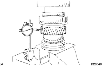
INSPECT 2ND GEAR THRUST CLEARANCE
-
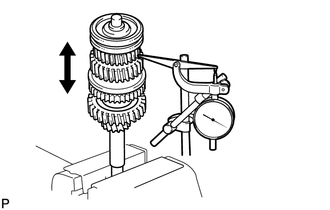
Using a dial indicator, measure the thrust clearance.
Standard clearance 0.10 to 0.25 mm (0.00394 to 0.00984 in.)
-
If the clearance is not as specified, replace the No. 1 synchronizer ring set.
-
-
-
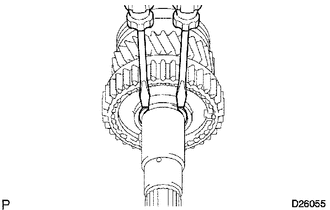
INSPECT 3RD GEAR THRUST CLEARANCE
-
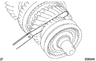
Using a feeler gauge, measure the thrust clearance.
Standard clearance 0.10 to 0.25 mm (0.00394 to 0.00984 in.)
-
If the clearance is not as specified, replace the No. 2 synchronizer ring set.
-
-
-
INSPECT 1ST GEAR RADIAL CLEARANCE
-
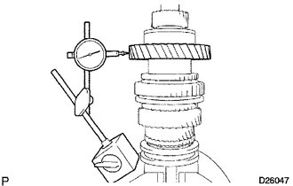
Using a dial indicator, measure the radial clearance.
Standard clearance 0.020 to 0.073 mm (0.000785 to 0.00287 in.)
-
If the clearance is not as specified, replace the 1st gear needle roller bearing with a new one.
-
-
-
INSPECT 2ND GEAR RADIAL CLEARANCE
-
Using a dial indicator, measure the radial clearance.
Standard clearance 0.015 to 0.068 mm (0.000591 to 0.00267 in.)
-
If the clearance is not as specified, replace the 2nd gear needle roller bearing with a new one.
-
-
-
INSPECT 3RD GEAR RADIAL CLEARANCE
-
Using a dial indicator, measure the radial clearance.
Standard clearance 0.015 to 0.068 mm (0.000591 to 0.00267 in.)
-
If the clearance is not as specified, replace the 3rd gear needle roller bearing with a new one.
-
-
-
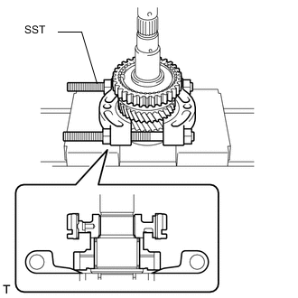
REMOVE 1ST GEAR
-
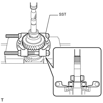
Using SST and a press, remove the 5th gear, output shaft center bearing, 1st gear thrust washer and 1st gear from the output shaft.
- SST
- 09950-00020
-
-
REMOVE NO. 1 SYNCHRONIZER RING SET (for 1st Gear)
-

Remove the synchronizer rings from the output shaft.
-
-
REMOVE 1ST GEAR THRUST WASHER PIN
-
Remove the thrust washer pin from the output shaft.
-
-
REMOVE 1ST GEAR NEEDLE ROLLER BEARING
-
Remove the needle roller bearing from the output shaft.
-
-
REMOVE 1ST GEAR BEARING SPACER
-
Remove the bearing spacer from the output shaft.
-
-
REMOVE BEARING SHAFT SNAP RING
-
Using 2 screwdrivers and a hammer, tap off the snap ring from the output shaft.
Note
Use a piece of cloth to prevent the snap ring from flying off.
-
-
REMOVE 2ND GEAR
-
Using SST and a press, remove the No. 1 transmission clutch hub with the reverse gear, the No. 1 synchronizer ring set and the 2nd gear from the output shaft.
- SST
- 09950-00020
-
-
REMOVE 2ND GEAR NEEDLE ROLLER BEARING
-
Remove the needle roller bearing from the output shaft.
-
-
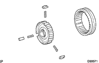
REMOVE REVERSE GEAR
-
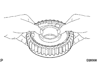
Remove the reverse gear, 3 No. 1 synchromesh shifting keys and 3 synchromesh shifting key springs.
Note
Use a piece of cloth to prevent the shifting keys and shifting key springs from popping out.
-
-
REMOVE CLUTCH HUB SET SHAFT SNAP RING
-
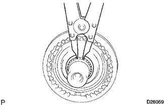
Using a snap ring expander, remove the snap ring from the output shaft.
Note
Do not damage the sliding surface of the bearing.
-
-
REMOVE 3RD GEAR
-
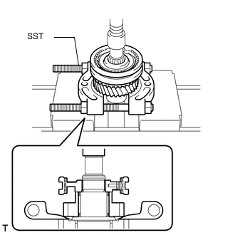
Using SST and a press, remove the No. 2 transmission clutch hub with the No. 2 transmission hub sleeve, the No. 2 synchronizer ring and the 3rd gear from the output shaft.
- SST
- 09950-00020
-
-
REMOVE 3RD GEAR NEEDLE ROLLER BEARING
-
Remove the needle roller bearing from the output shaft.
-
-
REMOVE NO. 2 TRANSMISSION HUB SLEEVE
-
Remove the No. 2 hub sleeve, 3 No. 2 synchromesh shifting key springs and 3 No. 2 synchromesh shifting keys from the No. 2 clutch hub.
-