MANUAL TRANSMISSION ASSEMBLY(for 1GD-FTV) INSTALLATION
PROCEDURE
-
INSTALL TRANSFER ASSEMBLY
-
INSTALL TRANSMISSION UPPER COVER SUB-ASSEMBLY
-
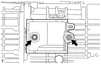
Install the transmission upper cover sub-assembly with the 2 bolts.
- Torque:
- 12 N*m { 117 kgf*cm, 8 ft.*lbf }
-
-
INSTALL MANUAL TRANSMISSION WITH TRANSFER
-
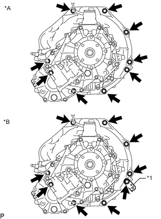
Text in Illustration *A w/o Urea SCR System *B w/ Urea SCR System *1 Wire Harness Bracket w/o Urea SCR System:
Install the manual transmission with transfer with the 9 bolts.
- Torque:
- 72 N*m { 729 kgf*cm, 53 ft.*lbf }
-
w/ Urea SCR System:
Install the manual transmission with transfer with the 9 bolts and wire harness bracket.
- Torque:
- 72 N*m { 729 kgf*cm, 53 ft.*lbf }
-
-
CONNECT TRANSFER AND MANUAL TRANSMISSION BREATHER HOSE SUB-ASSEMBLY
-
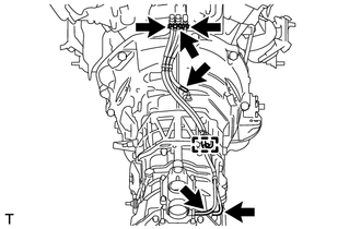
Connect the 3 breather hoses.
-
Attach the breather hose clamp.
-
-
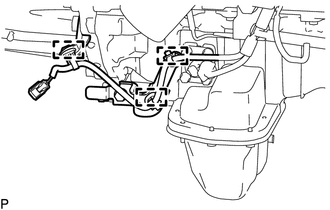
CONNECT WIRE HARNESS
-
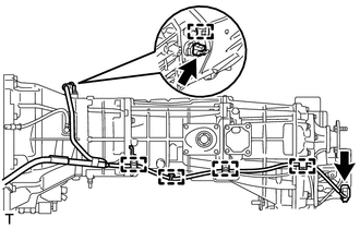
Attach the 5 wire harness clamps.
-
Connect the 2 connectors and wire harness.
-
-
INSTALL REAR NO. 1 ENGINE MOUNTING INSULATOR
-
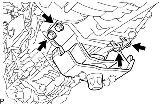
Install the rear No. 1 engine mounting insulator with the 4 bolts.
- Torque:
- 73 N*m { 739 kgf*cm, 54 ft.*lbf }
-
-
INSTALL FRONT ENGINE MOUNTING INSULATOR RH
-
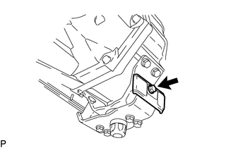
Install the front engine mounting insulator RH with the bolt.
- Torque:
- 12 N*m { 122 kgf*cm, 9 ft.*lbf }
-
-
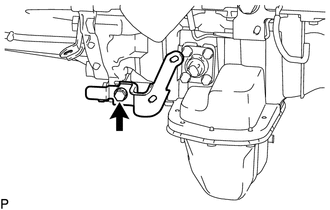
INSTALL NO. 3 FRAME CROSSMEMBER SUB-ASSEMBLY
-
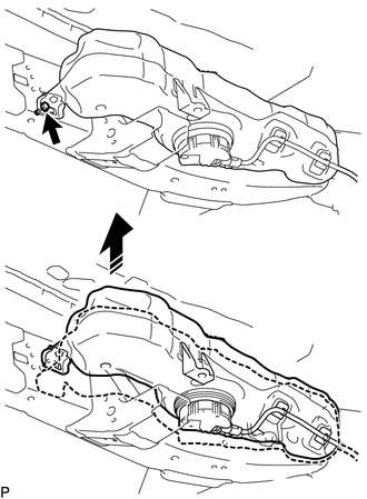
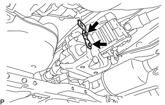
w/ Urea SCR System:
Remove the bolt as shown in the illustration, raise the urea tank sub-assembly and hold it in position.
Tech Tips
Only raise the urea tank enough to install the fixing bolt to the No. 3 frame crossmember sub-assembly. Do not raise it any higher.
-
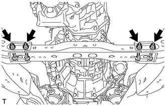
Install the No. 3 frame crossmember sub-assembly with the 4 bolts and 4 nuts.
- Torque:
- 72 N*m { 734 kgf*cm, 53 ft.*lbf }
-
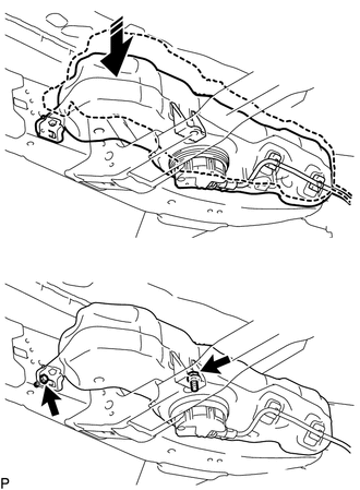
w/ Urea SCR System:
Connect the urea tank sub-assembly to the No. 3 frame crossmember sub-assembly with the 2 bolts.
- Torque:
- 14 N*m { 146 kgf*cm, 11 ft.*lbf }
-
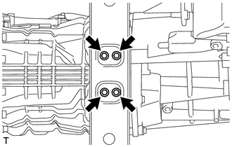
Install the 4 bolts to the No. 3 frame crossmember sub-assembly.
- Torque:
- 30 N*m { 306 kgf*cm, 22 ft.*lbf }
-
-
INSTALL FRONT SUSPENSION MEMBER BRACKET LH (w/o Urea SCR System)
-
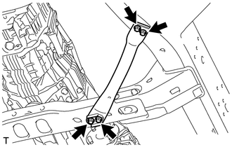
Install the front suspension member bracket LH with the 4 bolts.
- Torque:
- 33 N*m { 337 kgf*cm, 24 ft.*lbf }
-
-
INSTALL FRONT SUSPENSION MEMBER BRACKET LH (w/ Urea SCR System)
-
Install the front suspension member bracket LH with the 4 bolts.
- Torque:
- 33 N*m { 337 kgf*cm, 24 ft.*lbf }
-
-
INSTALL FRONT SUSPENSION MEMBER BRACKET RH
-
Install the front suspension member bracket RH with the 4 bolts.
- Torque:
- 33 N*m { 337 kgf*cm, 24 ft.*lbf }
-
-
INSTALL STARTER ASSEMBLY (w/o Urea SCR System)
-
for 2.0 kW Type: Click here
-
for 2.7 kW Type: Click here
-
-
CONNECT STARTER ASSEMBLY (w/ Urea SCR System)
-
for 2.0 kW Type:
Connect the starter assembly.
-
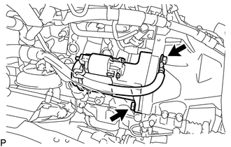
Connect the starter assembly with the 2 bolts.
- Torque:
- 68 N*m { 693 kgf*cm, 50 ft.*lbf }
-
Connect the starter wire with the nut.
- Torque:
- 9.8 N*m { 100 kgf*cm, 87 in.*lbf }
-
Connect the starter connector.
-
Close the terminal cap.
-
-
for 2.7 kW Type:
Connect the starter assembly.
-
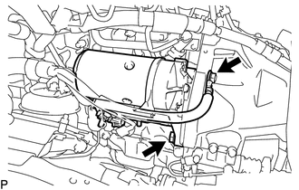
Connect the starter assembly with the 2 bolts.
- Torque:
- 68 N*m { 693 kgf*cm, 50 ft.*lbf }
-
Connect the starter wire with the nut.
- Torque:
- 21 N*m { 215 kgf*cm, 16 ft.*lbf }
-
Connect the starter connector.
-
Close the terminal cap.
-
-
-
INSTALL FRONT NO. 1 FENDER APRON TO FRAME SEAL LH
-
INSTALL CLUTCH RELEASE CYLINDER ASSEMBLY
-
INSTALL CLUTCH RELEASE CYLINDER TO FLEXIBLE HOSE TUBE
-
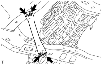
Install the clutch flexible hose bracket with the 2 bolts.
- Torque:
- 19 N*m { 194 kgf*cm, 14 ft.*lbf }
-
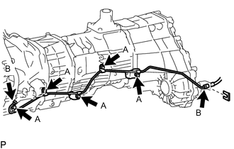
Temporarily install the clutch release cylinder to flexible hose tube with the 2 bolts, 3 nuts and a new clip.
-
Tighten the labeled A.
- Torque:
- 19 N*m { 194 kgf*cm, 14 ft.*lbf }
-
Tighten the labeled B.
- Torque:
- 15 N*m { 155 kgf*cm, 11 ft.*lbf }
-
-
INSTALL PROPELLER SHAFT ASSEMBLY
-
INSTALL FRONT PROPELLER SHAFT ASSEMBLY
-
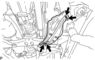
INSTALL OIL PAN INSULATOR
-
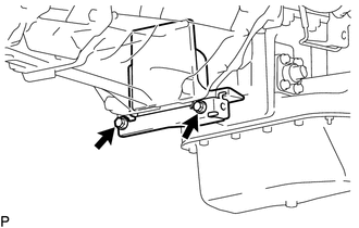
Install oil pan insulator with the 2 bolts.
- Torque:
- 18 N*m { 184 kgf*cm, 13 ft.*lbf }
-
-
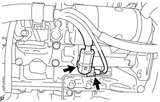
CONNECT WIRE HARNESS
-
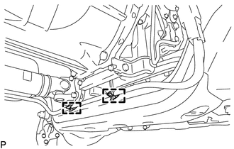
Attach the 2 wire harness clamps and connect the wire harness.
-
-
INSTALL WIRE HARNESS CLAMP BRACKET (w/ Urea SCR System)
-
Install the wire harness clamp bracket with the bolt.
- Torque:
- 13 N*m { 131 kgf*cm, 9 ft.*lbf }
-
Attach the 3 wire harness clamps and connect the wire harness.
-
-
INSTALL TRANSFER CASE LOWER PROTECTOR
-
Install the transfer case lower protector with the 4 bolts.
- Torque:
- 18 N*m { 184 kgf*cm, 13 ft.*lbf }
-
-
INSTALL FRONT EXHAUST PIPE ASSEMBLY
-
ADD MANUAL TRANSMISSION OIL
-
INSPECT MANUAL TRANSMISSION OIL
-
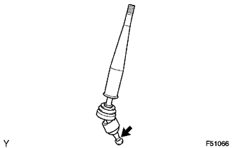
INSTALL SHIFT LEVER ASSEMBLY
-
Apply MP grease to the tip of the shift lever assembly.
Text in Illustration 
MP Grease -
Cover the shift lever cap with a cloth.
-
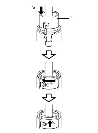
Text in Illustration *1 Shift Lever Cap *a Press down *b Clockwise *c Lock While pressing down on the shift lever cap, turn it clockwise to install the shift lever assembly.
-
Attach the shift lever cap boot.
-
-
INSTALL NO. 1 SHIFT AND SELECT LEVER BOOT
-
Install the No. 1 shift and select lever boot with the 4 screws.
-
-
INSTALL CONSOLE BOX ASSEMBLY
-
for manual transmission: Click here
-
w/ Refrigerated Cool Box: Click here
-
-
FILL RESERVOIR WITH BRAKE FLUID
-
BLEED CLUTCH LINE
-
INSPECT FLUID LEVEL IN RESERVOIR
-
INSPECT FOR BRAKE FLUID LEAK FROM CLUTCH LINE
-
CONNECT CABLE TO NEGATIVE BATTERY TERMINAL
Note
When disconnecting the cable, some systems need to be initialized after the cable is reconnected Click here.