MANUAL TRANSMISSION ASSEMBLY(for 1GD-FTV) REMOVAL
PROCEDURE
-
DISCONNECT CABLE FROM NEGATIVE BATTERY TERMINAL
Note
-
After turning the ignition switch off, waiting time may be required before disconnecting the cable from the battery terminal. Therefore, make sure to read the disconnecting the cable from the battery terminal notice before proceeding with work Click here.
-
When disconnecting the cable, some systems need to be initialized after the cable is reconnected Click here.
-
-
REMOVE CONSOLE BOX ASSEMBLY
-
for Manual Transmission: Click here
-
w/ Refrigerated Cool Box: Click here
-
-
REMOVE NO. 1 SHIFT AND SELECT LEVER BOOT
-
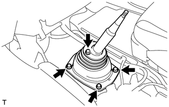
Remove the 4 screws and No. 1 shift and select lever boot.
-
-
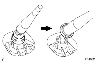
REMOVE SHIFT LEVER ASSEMBLY
-
Detach the shift lever cap boot from the manual transmission.
-
Cover the shift lever cap with a cloth.
-
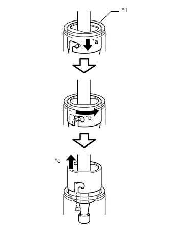
Text in Illustration *1 Shift Lever Cap *a Press Down *b Counterclockwise *c Pull out While pressing down on the shift lever cap, turn it counterclockwise, and then pull to remove the shift lever assembly.
-
-
DRAIN BRAKE FLUID FROM CLUTCH LINE
-
DRAIN MANUAL TRANSMISSION OIL
-
Remove the drain plug and gasket, and then drain the manual transmission oil.
-
Install a new gasket and the drain plug.
- Torque:
- 37 N*m { 377 kgf*cm, 27 ft.*lbf }
-
-
REMOVE FRONT EXHAUST PIPE ASSEMBLY
-
REMOVE TRANSFER CASE LOWER PROTECTOR
-
Remove the 4 bolts and transfer case lower protector.
-
-
REMOVE WIRE HARNESS CLAMP BRACKET (w/ Urea SCR System)
-
Detach the 3 wire harness clamps and disconnect the wire harness.
-
Remove the bolt and wire harness clamp bracket.
-
-
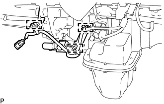
DISCONNECT WIRE HARNESS (w/ Urea SCR System)
-
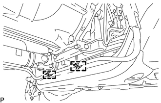
Detach the 2 wire harness clamps and disconnect the wire harness.
-
-
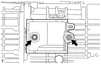
REMOVE OIL PAN INSULATOR
-
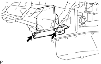
Remove the 2 bolts and oil pan insulator.
-
-
REMOVE FRONT PROPELLER SHAFT ASSEMBLY
-
REMOVE PROPELLER SHAFT ASSEMBLY
-
REMOVE CLUTCH RELEASE CYLINDER TO FLEXIBLE HOSE TUBE
-
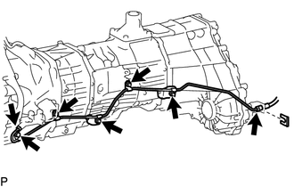
Remove the 2 bolts, 3 nut, clip and clutch release cylinder to flexible hose tube.
-
Remove the 2 bolts and clutch flexible hose bracket.
-
-
REMOVE CLUTCH RELEASE CYLINDER ASSEMBLY
-
REMOVE FRONT NO. 1 FENDER APRON TO FRAME SEAL LH (w/ Urea SCR System)
-
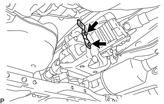
DISCONNECT STARTER ASSEMBLY (w/ Urea SCR System)
-
for 2.0 kW Type:
Disconnect the starter.
-
Open the terminal cap.
-
Remove the nut and disconnect the starter wire.
-
Disconnect the starter connector.
-
Remove the 2 bolts and disconnect the starter assembly.
-
-
for 2.7 kW Type:
Disconnect the starter.
-
Open the terminal cap.
-
Remove the nut and disconnect the starter wire.
-
Disconnect the starter connector.
-
Remove the 2 bolts and disconnect the starter assembly.
-
-
-
REMOVE STARTER ASSEMBLY (w/o Urea SCR System)
-
for 2.0 kW Type: Click here
-
for 2.7 kW Type: Click here
-
-
REMOVE FRONT SUSPENSION MEMBER BRACKET LH
-
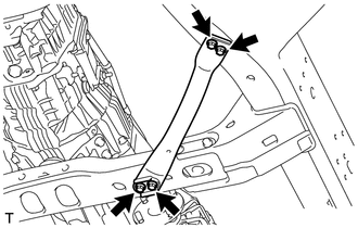
Remove the 4 bolts and front suspension member bracket LH.
-
-
REMOVE FRONT SUSPENSION MEMBER BRACKET LH (w/ Urea SCR System)
-
Remove the 4 bolts and front suspension member bracket LH.
-
-
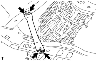
REMOVE FRONT SUSPENSION MEMBER BRACKET RH
-
Remove the 4 bolts and front suspension member bracket RH.
-
-
REMOVE NO. 3 FRAME CROSSMEMBER SUB-ASSEMBLY
-
Support the rear side of the manual transmission with a support stand.
-
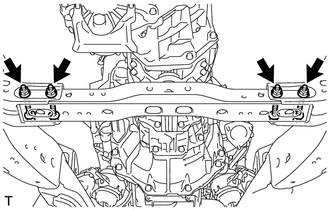
Remove the 4 bolts from the No. 3 frame crossmember sub-assembly.
-
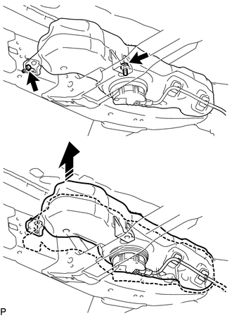
w/ Urea SCR System:
Remove the 2 bolts as shown in the illustration, raise the urea tank sub-assembly and hold it in position.
Tech Tips
Only raise the urea tank enough to remove the fixing bolts on the No. 3 frame crossmember sub-assembly. Do not raise it any higher.
-
Remove the 4 nuts, 4 bolts and No. 3 frame crossmember sub-assembly.
-
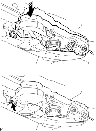
w/ Urea SCR System:
Temporarily install the urea tank sub-assembly with the bolt as shown in the illustration.
-
-
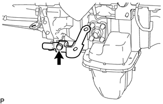
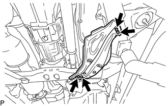
REMOVE FRONT ENGINE MOUNTING INSULATOR RH
-
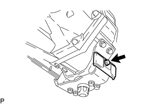
Remove the bolt and front engine mounting insulator RH.
-
-
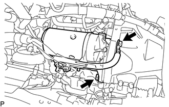
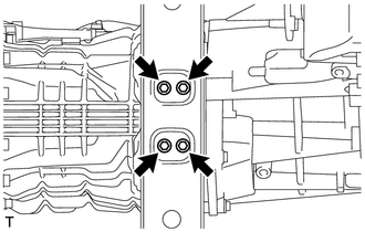
REMOVE REAR NO. 1 ENGINE MOUNTING INSULATOR
-
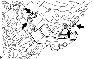
Remove the 4 bolts and rear No. 1 engine mounting insulator from the manual transmission.
-
-
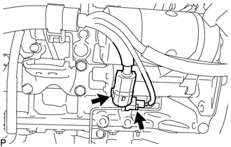
DISCONNECT WIRE HARNESS
-
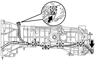
Detach the 5 wire harness clamps.
-
Disconnect the 2 connectors and wire harness.
-
-
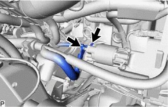
DISCONNECT TRANSFER AND MANUAL TRANSMISSION BREATHER HOSE SUB-ASSEMBLY
-
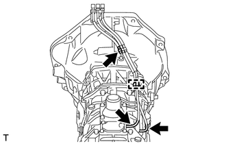
Detach the breather hose clamp.
-
Disconnect the 3 breather hoses.
-
-
REMOVE MANUAL TRANSMISSION WITH TRANSFER
-
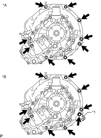
Text in Illustration *A w/o Urea SCR System *B w/ Urea SCR System *1 Wire Harness Bracket w/o Urea SCR System:
Remove the 9 bolts.
-
w/ Urea SCR System:
Remove the 9 bolts and wire harness bracket.
-
Remove the manual transmission with transfer.
-
-
REMOVE TRANSMISSION UPPER COVER SUB-ASSEMBLY
-
Remove the 2 bolts and transmission upper cover sub-assembly.
-
-
REMOVE TRANSFER ASSEMBLY