OIL COOLER(for 2TR-FE) INSTALLATION
PROCEDURE
-
INSTALL OIL COOLER TUBE SUB-ASSEMBLY
-
Install the 2 oil cooler tube clamps with the 2 bolts.
- Torque:
- 14 N*m { 143 kgf*cm, 10 ft.*lbf }
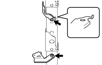
Note
Make contact with the terminal stopper.
-
Install the 2 flexible hose clamps, No. 2 oil cooler inlet tube and No. 2 oil cooler outlet tube with the 2 bolt.
- Torque:
- 5.5 N*m { 56 kgf*cm, 49 in.*lbf }
-
-
INSTALL OIL COOLER HOSE
Note
-
When disconnecting the hoses from the tube, support the tube by hand and be careful to prevent the tube from being deformed.
-
Make sure to install the clips so that the spool fitting is not overlapped.
-
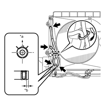
Text in Illustration *a Front Side *b 2 to 7 mm (0.0788 to 0.2755 in.) Install the No. 1 transmission oil cooler hose and No. 2 transmission oil cooler hose to the radiator, and slide the 2 clips to secure them.
Tech Tips
Position the claws of the clips so that they do not interfere with other parts unless otherwise specified.
-
Connect the No. 1 transmission oil cooler hose and No. 2 transmission oil cooler hose to the oil cooler tube sub-assembly, and slide the 2 clips to secure them.
-
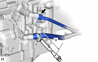
Then pass the No. 1 transmission oil cooler hose and No. 2 transmission oil cooler hose through the No. 1 flexible hose clamp and close the No. 1 flexible hose clamp.
-
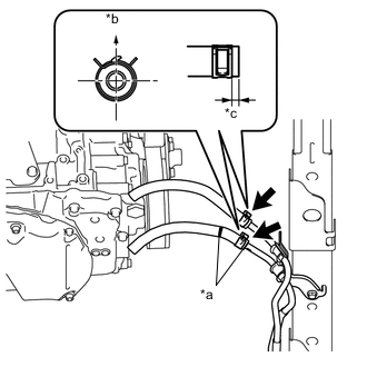
Text in Illustration *a Paint Mark *b Upper Side *c 2 to 7 mm (0.0788 to 0.2755 in.) Install the No. 1 oil cooler inlet hose and No. 1 oil cooler outlet hose to the oil cooler tube sub-assembly, and slide the 2 clips to secure them.
-
-
INSTALL NO. 1 OIL COOLER INLET TUBE AND NO. 1 OIL COOLER OUTLET TUBE
Note
-
When disconnecting the hoses from the tube, support the tube by hand and be careful to prevent the tube from being deformed.
-
Make sure to install the clips so that the spool fitting is not overlapped.
-
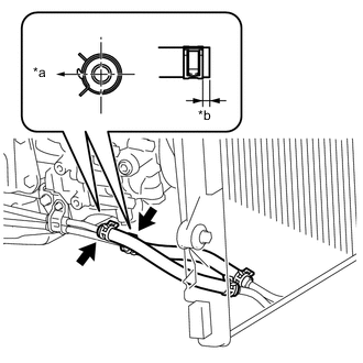
Install the 2 oil cooler tube clamps to the engine assembly with the 2 bolts.
- Torque:
- for Bolt A
- 14 N*m { 143 kgf*cm, 10 ft.*lbf }
- for Bolt B
- 28 N*m { 286 kgf*cm, 21 ft.*lbf }
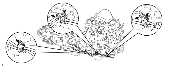
Text in Illustration *1 Flexible Hose Clamp *2 Oil Cooler Tube Clamp -
Connect the ends of the No. 1 oil cooler inlet tube and No. 1 oil cooler outlet tube to the automatic transmission assembly by hand.
-
Close the 2 oil cooler tube clamps and install the 2 bolts.
- Torque:
- 5.5 N*m { 56 kgf*cm, 49 in.*lbf }
-
Install the flexible hose clamp to the automatic transmission assembly with the bolt.
- Torque:
- 14 N*m { 143 kgf*cm, 10 ft.*lbf }
-
Text in Illustration *a LH Side *b 2 to 7 mm (0.0788 to 0.2755 in.) Connect the No. 1 oil cooler inlet hose and No. 1 oil cooler outlet hose to the No. 1 oil cooler inlet tube and No. 1 oil cooler outlet tube, and slide the 2 clips to secure them.
-
Text in Illustration *a Torque Wrench Fulcrum Length Using a 17 mm union nut wrench, tighten the No. 1 oil cooler inlet tube and No. 1 oil cooler outlet tube.
- Torque:
- Specified tightening torque
- 34 N*m { 350 kgf*cm, 25 ft.*lbf }
Tech Tips
-
Calculate the torque wrench reading when changing the fulcrum length of the torque wrench.
-
When using a union nut wrench (fulcrum length of 30 mm (1.181 in.)) + torque wrench (fulcrum length of 180 mm (7.087 in.)): 29 N*m (300 kgf*cm, 22 ft.*lbf)
-
-
ADJUST AUTOMATIC TRANSMISSION FLUID LEVEL
-
Adjust the automatic transmission fluid level Click here.
-
-
INSTALL FRONT EXHAUST PIPE ASSEMBLY
-
INSTALL REAR ENGINE UNDER COVER ASSEMBLY
-
INSTALL NO. 1 ENGINE UNDER COVER SUB-ASSEMBLY