OIL COOLER(for 1GR-FE) INSTALLATION
PROCEDURE
-
INSTALL OIL COOLER ASSEMBLY (w/ Air Cooled Transmission Oil Cooler)
-
Install the 2 oil cooler brackets to the oil cooler assembly with the 2 bolts.
- Torque:
- 5.5 N*m { 56 kgf*cm, 49 in.*lbf }
-
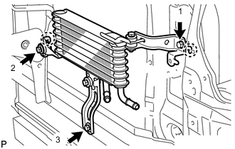
Attach the 2 claws and install the oil cooler assembly to the vehicle body with the 3 bolts in the order shown in the illustration.
- Torque:
- 5.5 N*m { 56 kgf*cm, 49 in.*lbf }
-
-
INSTALL NO. 3 OIL COOLER TUBE SUB-ASSEMBLY (w/ Air Cooled Transmission Oil Cooler)
-
Pass the No. 3 oil cooler tube sub-assembly through the hole of vehicle body from the rear of the vehicle and install it to the oil cooler bracket with the bolt.
- Torque:
- 5.5 N*m { 56 kgf*cm, 49 in.*lbf }
-
-
INSTALL NO. 6 INLET OIL COOLER HOSE AND NO.6 OUTLET OIL COOLER HOSE (w/ Air Cooled Transmission Oil Cooler)
Note
-
When disconnecting the hoses from the tube, support the tube by hand and be careful to prevent the tube from being deformed.
-
Make sure to install the clips so that the spool fitting is not overlapped.
-
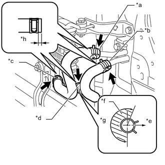
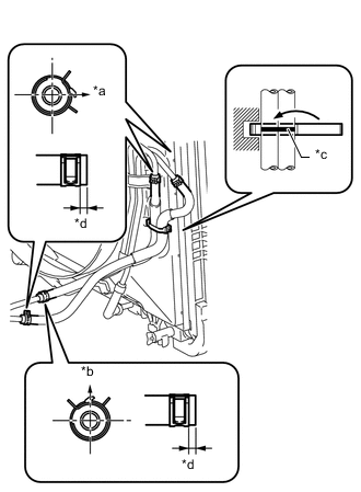
Text in Illustration *a Blue Paint Mark *b Pink Paint Mark *c Yellow Paint Mark *d White Paint Mark *e Front Side *f No hose clamp claw in this region *g 205° *h 2 to 7 mm (0.0788 to 0.2755 in.) Install the No. 6 oil cooler inlet hose and No. 6 oil cooler outlet hose to the oil cooler, and slide the 2 clips to secure them.
Note
Make sure to install any hose clips without a specific installation direction in a direction that does not interfere with other parts.
-
Connect the No. 6 oil cooler inlet hose and No. 6 oil cooler outlet hose to the No. 3 oil cooler tube sub-assembly, and slide the 2 clips to secure them.
Note
Make sure to install any hose clips without a specific installation direction in a direction that does not interfere with other parts.
-
-
INSTALL NO. 2 OIL COOLER TUBE SUB-ASSEMBLY
-
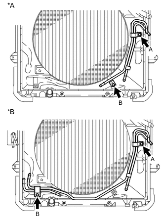
Text in Illustration *A w/o Air Cooled Transmission Oil Cooler *B w/ Air Cooled Transmission Oil Cooler Temporarily install the oil cooler tube to the fan shroud with bolt labeled A. Install bolt labeled B and tighten it to the specified torque. Then tighten bolt labeled A to the specified torque.
- Torque:
- 5.5 N*m { 56 kgf*cm, 49 in.*lbf }
-
-
INSTALL NO. 5 OIL COOLER INLET HOSE AND NO. 5 OIL COOLER OUTLET HOSE (w/ Air Cooled Transmission Oil Cooler)
Note
-
When disconnecting the hoses from the tube, support the tube by hand and be careful to prevent the tube from being deformed.
-
Make sure to install the clips so that the spool fitting is not overlapped.
-
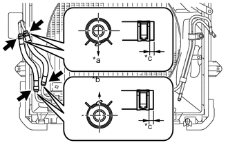
Text in Illustration *a Rear Side *b Front Side *c 2 to 7 mm (0.0788 to 0.2755 in.) Install the No. 5 oil cooler inlet hose and No. 5 oil cooler outlet hose to the No. 2 oil cooler tube sub-assembly, and slide the 2 clips to secure them.
-
Connect the No. 5 oil cooler inlet hose and No. 5 oil cooler outlet hose to the No. 3 oil cooler tube sub-assembly, and slide the 2 clips to secure them.
-
-
INSTALL NO. 4 OIL COOLER INLET HOSE AND NO. 4 OIL COOLER OUTLET HOSE
Note
-
When disconnecting the hoses from the tube, support the tube by hand and be careful to prevent the tube from being deformed.
-
Make sure to install the clips so that the spool fitting is not overlapped.
-
Install the No. 4 oil cooler inlet hose and No. 4 oil cooler outlet hose to the No. 2 oil cooler tube, and slide the 2 clips to secure them.
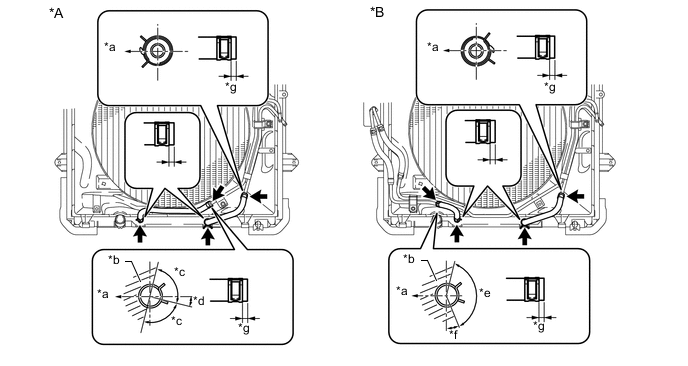
Text in Illustration *A w/o Air Cooled Transmission Oil Cooler *B w/ Air Cooled Transmission Oil Cooler *a Rear Side *b No hose clamp claw in this region *c 90° *d 17.6° *e 130° *f 33.2° *g 2 to 7 mm (0.0788 to 0.2755 in.) - - -
Connect the No. 4 oil cooler inlet hose and No. 4 oil cooler outlet hose to the radiator, and slide the 2 clips to secure them.
Note
Make sure to install any hose clips without a specific installation direction in a direction that does not interfere with other parts.
-
-
INSTALL NO. 1 OIL COOLER INLET TUBE AND NO. 1 OIL COOLER OUTLET TUBE (w/o Air Cooled Transmission Oil Cooler)
-
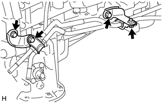
Install the 2 oil cooler tube clamps to the automatic transmission assembly and engine assembly with the 2 bolts.
- Torque:
- 14 N*m { 143 kgf*cm, 10 ft.*lbf }
-
Install the No. 1 oil cooler inlet tube, No. 1 oil cooler outlet tube and 2 flexible hose clamps to the 2 oil cooler tube clamps with the 2 bolts.
- Torque:
- 5.5 N*m { 56 kgf*cm, 49 in.*lbf }
-
-
INSTALL NO. 1 OIL COOLER INLET TUBE AND NO. 1 OIL COOLER OUTLET TUBE (w/ Air Cooled Transmission Oil Cooler)
-
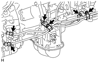
Install the 2 oil cooler tube clamps to the automatic transmission and engine assembly with the 2 bolts.
- Torque:
- 14 N*m { 143 kgf*cm, 10 ft.*lbf }
-
Connect the ends of the No. 1 oil cooler inlet tube and No. 1 oil cooler outlet tube to the automatic transmission assembly by hand.
-
Close the 2 oil cooler tube clamps and install the 2 bolts.
- Torque:
- 5.5 N*m { 56 kgf*cm, 49 in.*lbf }
-
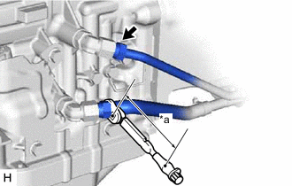
Text in Illustration *a Torque Wrench Fulcrum Length Using a 17 mm union nut wrench, tighten the No. 1 oil cooler inlet tube and No. 1 oil cooler outlet tube.
- Torque:
- Specified tightening torque
- 34 N*m { 350 kgf*cm, 25 ft.*lbf }
Tech Tips
-
Calculate the torque wrench reading when changing the fulcrum length of the torque wrench.
-
When using a union nut wrench (fulcrum length of 30 mm (1.181 in.)) + torque wrench (fulcrum length of 180 mm (7.087 in.)): 29 N*m (300 kgf*cm, 22 ft.*lbf)
-
-
INSTALL NO. 3 OIL COOLER INLET HOSE AND NO. 3 OIL COOLER OUTLET HOSE
Note
-
When disconnecting the hoses from the tube, support the tube by hand and be careful to prevent the tube from being deformed.
-
Make sure to install the clips so that the spool fitting is not overlapped.
-
Text in Illustration *a RH Side *b Upper Side *c Paint Mark *d 2 to 7 mm (0.0788 to 0.2755 in.) Install the No. 3 oil cooler inlet hose and No. 3 oil cooler outlet hose to the No. 1 oil cooler inlet tube and No. 1 oil cooler outlet tube, and slide the 2 clips to secure them.
-
Connect the No. 3 oil cooler inlet hose and No. 3 oil cooler outlet hose to the No. 2 oil cooler tube sub-assembly, and slide the 2 clips to secure them.
-
Then pass the No. 3 oil cooler inlet hose and No. 3 oil cooler outlet hose through the clamp and close the clamp.
-
-
INSTALL TRANSMISSION OIL COOLER ASSEMBLY (w/o Air Cooled Transmission Oil Cooler)
Note
Make sure to install the clips so that the spool fitting is not overlapped.
-
Coat 2 new O-rings with ATF, and install them to the transmission oil cooler assembly.
-
Align the transmission oil cooler with the transmission oil thermostat and assemble them with the 3 bolts.
- Torque:
- 14 N*m { 143 kgf*cm, 10 ft.*lbf }
-
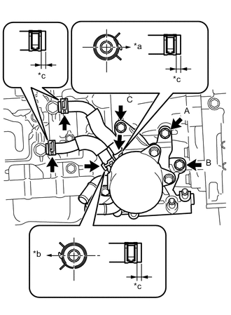
Text in Illustration *a Front Side *b Rear Side *c 2 to 7 mm (0.0788 to 0.2755 in.) Temporarily install the transmission oil cooler together with the transmission oil thermostat with bolt labeled A. Install bolts labeled B and labeled C and tighten them to the specified torque. Then tighten bolt labeled A to the specified torque.
- Torque:
- 21 N*m { 214 kgf*cm, 15 ft.*lbf }
-
Install the No. 1 oil cooler inlet hose and No. 1 oil cooler outlet hose to the transmission oil thermostat, and slide the 2 clips to secure them.
-
Connect the No. 1 oil cooler inlet hose and No. 1 oil cooler outlet hose to the automatic transmission assembly, and slide the 2 clips to secure them.
Note
Make sure to install any hose clips without a specific installation direction in a direction that does not interfere with other parts.
-
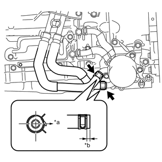
Text in Illustration *a RH Side *b 2 to 7 mm (0.0788 to 0.2755 in.) Connect the 2 water by-pass hoses to the transmission oil cooler assembly, and slide the 2 clips to secure them.
-
-
INSTALL NO. 2 OIL COOLER INLET HOSE AND NO. 2 OIL COOLER OUTLET HOSE (w/o Air Cooled Transmission Oil Cooler)
Note
-
When disconnecting the hoses from the tube, support the tube by hand and be careful to prevent the tube from being deformed.
-
Make sure to install the clips so that the spool fitting is not overlapped.
-
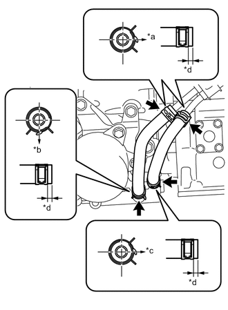
Text in Illustration *a RH Side *b Lower Side *c Front Side *d 2 to 7 mm (0.0788 to 0.2755 in.) Install the No. 2 oil cooler inlet hose and No. 2 oil cooler outlet hose to the transmission oil thermostat, and slide the 2 clips to secure them.
-
Connect the No. 2 oil cooler inlet hose and No. 2 oil cooler outlet hose to the No. 1 oil cooler inlet tube and No. 1 oil cooler outlet tube, and slide the 2 clips to secure them.
-
-
INSTALL EXHAUST MANIFOLD SUB-ASSEMBLY RH
-
ADD ENGINE COOLANT (w/o Air Cooled Transmission Oil Cooler)
-
ADJUST AUTOMATIC TRANSMISSION FLUID LEVEL
-
INSPECT FOR COOLANT LEAK
-
INSTALL FRONT BUMPER COVER (w/ Air Cooled Transmission Oil Cooler)
-
INSTALL NO. 1 ENGINE UNDER COVER SUB-ASSEMBLY
-
INSTALL REAR ENGINE UNDER COVER ASSEMBLY