AUTOMATIC TRANSMISSION SYSTEM(for 2TR-FE) Pattern Select Switch 2nd Start Mode Circuit
DESCRIPTION
When 2nd start mode is selected with the pattern select switch assembly (2nd start), the ECM controls the solenoid valves and the transmission starts from 2nd gear.
In 2nd start mode, the system operates the throttle motor to control engine output to reduce skidding of the drive wheels and guarantee stable acceleration from rest, straight driving and turning stability.
When the shift lever is in D, the transmission automatically shifts up from 2nd to 6th as usual.
Tech Tips
-
The pattern select switch assembly (2nd start) is a momentary-type switch.
-
In order to cancel 2nd start mode, push the pattern select switch assembly (2nd start) again or turn the ignition switch off.
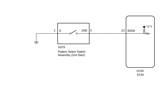
WIRING DIAGRAM
PROCEDURE
-
INSPECT PATTERN SELECT SWITCH ASSEMBLY (2ND START)
-
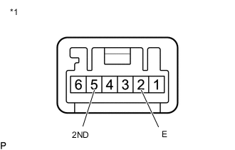
Text in Illustration *1 Pattern Select Switch Assembly (2nd Start) Remove the pattern select switch assembly (2nd start) Click here.
-
Measure the resistance according to the value(s) in the table below.
Standard Resistance Tester Connection Switch Condition Specified Condition 5 (2ND) - 2 (E) 2ND START switch pushed and held Below 1 Ω 5 (2ND) - 2 (E) 2ND START switch not pushed 10 kΩ or higher
NG 
REPLACE PATTERN SELECT SWITCH ASSEMBLY (2ND START) Click here
OK 
-
-
CHECK HARNESS AND CONNECTOR (PATTERN SELECT SWITCH ASSEMBLY (2ND START) - BODY GROUND)
-
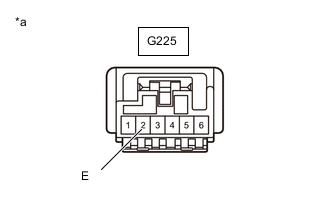
Text in Illustration *a Front view of wire harness connector
(to Pattern Select Switch Assembly (2nd Start))
Disconnect the pattern select switch assembly (2nd start) connector.
-
Measure the resistance according to the value(s) in the table below.
Standard Resistance Tester Connection Condition Specified Condition G225-2 (E) - Body ground Always Below 1 Ω
NG
REPAIR OR REPLACE HARNESS OR CONNECTOR
OK
-
-
CHECK HARNESS AND CONNECTOR (PATTERN SELECT SWITCH ASSEMBLY (2ND START) - ECM)
-
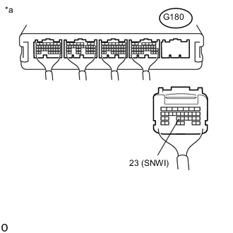
Text in Illustration *a Rear view of wire harness connector
(to ECM)
Disconnect the ECM connector.
-
Measure the resistance according to the value(s) in the table below.
Standard Resistance Tester Connection Switch Condition Specified Condition G180-23 (SNWI) - Body ground 2ND START switch switch pushed and held Below 1 Ω G180-23 (SNWI) - Body ground 2ND START switch switch not pushed 10 kΩ or higher
OK
PROCEED TO NEXT SUSPECTED AREA SHOWN IN PROBLEM SYMPTOMS TABLE Click here
NG
REPAIR OR REPLACE HARNESS OR CONNECTOR
-