AUTOMATIC TRANSMISSION SYSTEM(for 1GD-FTV) Pattern Select Switch Sport Mode Circuit
DESCRIPTION
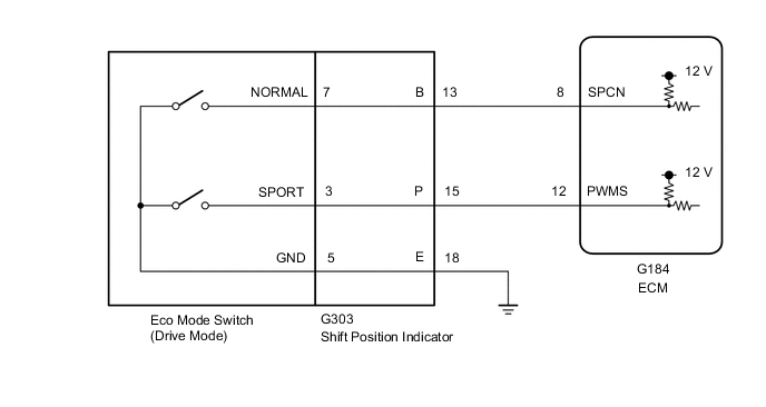
The ECM memory contains the programs for the normal and sport shift patterns and lock-up pattern.
By following the programs corresponding to the signals from the SPORT mode switch (eco mode switch (drive mode)), the park/neutral position switch and other various sensors, the ECM switches the solenoid valves on and off, and controls the transmission gear change and the lock-up clutch operation.
WIRING DIAGRAM
PROCEDURE
-
CHECK HARNESS AND CONNECTOR (SHIFT POSITION INDICATOR - BODY GROUND)
-
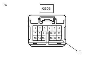
Text in Illustration *a Front view of wire harness connector
(to Shift Position Indicator)
Disconnect the shift position indicator connector.
-
Measure the resistance according to the value(s) in the table below.
Standard Resistance Tester Connection Condition Specified Condition G303-18 (E) - Body ground Always Below 1 Ω
NG 
REPAIR OR REPLACE HARNESS OR CONNECTOR
OK 
-
-
CHECK SHIFT POSITION INDICATOR
-
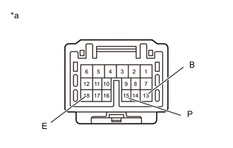
Text in Illustration *a Component without harness connected
(Shift Position Indicator)
Disconnect the shift position indicator connector.
-
Measure the resistance according to the value(s) in the table below.
Standard Resistance Tester Connection Switch Condition Specified Condition 15 (P) - 18 (E) SPORT mode switch pushed and held Below 10 Ω SPORT mode switch not pushed 10 kΩ or higher 13 (B) - 18 (E) NORMAL mode switch pushed and held Below 10 Ω NORMAL mode switch not pushed 10 kΩ or higher
NG 
INSPECT ECO MODE SWITCH (DRIVE MODE) Click here
OK
-
-
CHECK HARNESS AND CONNECTOR (SHIFT POSITION INDICATOR - ECM)
-
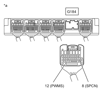
Text in Illustration *a Rear view of wire harness connector
(to ECM)
Disconnect the ECM connector.
-
Measure the resistance according to the value(s) in the table below.
Standard Resistance Tester Connection Switch Condition Specified Condition G184-12 (PWMS) - Body ground SPORT mode switch pushed and held Below 10 Ω SPORT mode switch not pushed 10 kΩ or higher G184-8 (SPCN) - Body ground NORMAL mode switch pushed and held Below 10 Ω NORMAL mode switch not pushed 10 kΩ or higher
OK
PROCEED TO NEXT SUSPECTED AREA SHOWN IN PROBLEM SYMPTOMS TABLE Click here
NG
REPAIR OR REPLACE HARNESS OR CONNECTOR
-
-
INSPECT ECO MODE SWITCH (DRIVE MODE)
-
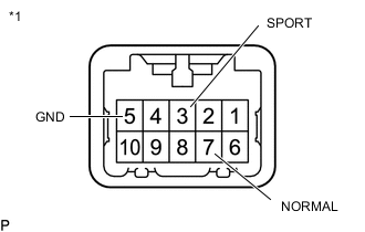
Text in Illustration *1 Eco Mode Switch (Drive Mode) Remove the eco mode switch (drive mode) connector Click here.
-
Measure the resistance according to the value(s) in the table below.
Standard Resistance Tester Connection Switch Condition Specified Condition 3 (SPORT) - 5 (GND) SPORT mode switch pushed and held Below 10 Ω SPORT mode switch not pushed 10 kΩ or higher 7 (NORMAL) - 5 (GND) NORMAL mode switch pushed and held Below 10 Ω NORMAL mode switch not pushed 10 kΩ or higher
OK
REPLACE SHIFT POSITION INDICATOR Click here
NG
REPLACE ECO MODE SWITCH (DRIVE MODE) Click here
-