COMBINATION SWITCH INSPECTION
PROCEDURE
-
INSPECT COMBINATION SWITCH ASSEMBLY (w/ Module Switch (2nd Start))
-
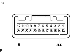
*a Component without harness connected
(Combination Switch Assembly (w/ Module Switch (2nd Start)))
Measure the resistance according to the value(s) in the table below.
Standard Resistance Tester Connection Switch Condition Specified Condition 14 (2ND) - 24 (E) Combination switch (2nd Start) pushed and held Below 1 Ω Combination switch (2nd Start) not pushed 10 kΩ or higher If the result is not as specified, replace the combination switch assembly (w/ Module Switch (2nd Start)).
-
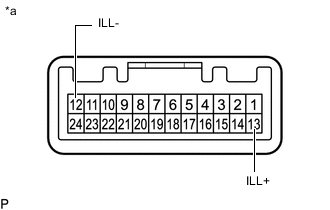
*a Component without harness connected
(Combination Switch Assembly (w/ Module Switch (2nd Start)))
Apply battery voltage between the terminals of the combination switch assembly (w/ Module Switch (2nd Start)), and check the illumination condition of the combination switch assembly (w/ Module Switch (2nd Start)).
OK Measurement Condition Specified Condition Battery positive (+) → 13 (ILL+)
Battery negative (-) → 12 (ILL-)
Illuminates If the result is not as specified, replace the combination switch assembly (w/ Module Switch (2nd Start)).
-
-
INSPECT NO. 2 COMBINATION SWITCH ASSEMBLY (w/o Module Switch (2nd Start))
-
*a Component without harness connected
(No. 2 Combination Switch Assembly (w/o Module Switch (2nd Start)))
Measure the resistance according to the value(s) in the table below.
Standard Resistance Tester Connection Switch Condition Specified Condition 14 (2ND) - 24 (E) No. 2 combination switch (2nd Start) pushed and held Below 1 Ω No. 2 combination switch (2nd Start) not pushed 10 kΩ or higher If the result is not as specified, replace the No. 2 combination switch assembly (w/o Module Switch (2nd Start)).
-
*a Component without harness connected
(No. 2 Combination Switch Assembly (w/o Module Switch (2nd Start)))
Apply battery voltage between the terminals of the No. 2 combination switch assembly (w/o Module Switch (2nd Start)), and check the illumination condition of the No. 2 combination switch assembly (w/o Module Switch (2nd Start)).
OK Measurement Condition Specified Condition Battery positive (+) → 13 (ILL+)
Battery negative (-) → 12 (ILL-)
Illuminates If the result is not as specified, replace the No. 2 combination switch assembly (w/o Module Switch (2nd Start)).
-