AUTOMATIC TRANSMISSION SYSTEM(for 1KD-FTV) ECU Power Source Circuit
DESCRIPTION
When the ignition switch is turned to ON, battery voltage is applied to terminal IG2 of the TCM.
WIRING DIAGRAM
Refer to DTC P0560 Click here.
CAUTION / NOTICE / HINT
Note
Inspect the fuses for circuits related to this system before performing the following inspection procedure.
PROCEDURE
-
CHECK TCM (TCM - BODY GROUND)
-
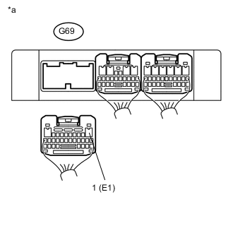
Text in Illustration *a Rear view of wire harness connector
(to TCM)
Disconnect the G69 TCM connector.
-
Measure the resistance according to the value(s) in the table below.
Standard Resistance Tester Connection Condition Specified Condition G69-1 (E1) - Body ground Always Below 1 Ω
NG 
REPAIR OR REPLACE HARNESS OR CONNECTOR
OK 
-
-
CHECK HARNESS AND CONNECTOR (NO. 1 INTEGRATION RELAY - TCM)
-
Disconnect the No. 1 integration relay 1A connector.
-
Disconnect the G70 TCM connector.
-
Measure the resistance according to the value(s) in the table below.
Standard Resistance Tester Connection Condition Specified Condition 1A-4 - G70-6 (IG2) Always Below 1 Ω 1A-4 or G70-6 (IG2) - Body ground Always 10 kΩ or higher
OK
GO TO ECD SYSTEM (ECM POWER SOURCE CIRCUIT) Click here
NG
REPAIR OR REPLACE HARNESS OR CONNECTOR
-