AUTOMATIC TRANSMISSION SYSTEM(for 1KD-FTV), Diagnostic DTC:P0724

| DTC Code | DTC Name |
|---|---|
| P0724 | Brake Switch "B" Circuit High |
DESCRIPTION
The purpose of this circuit is to prevent the engine from stalling while driving in lock-up when the brakes are suddenly applied.
When the brake pedal is depressed, this switch sends a signal to the TCM. Then the TCM cancels the operation of the lock-up clutch while braking is in progress.
| DTC Code | DTC Detection Condition | Trouble Area |
|---|---|---|
| P0724 | Stop light switch remains on even when the vehicle is driven in a stop (less than 3 km/h (2 mph)) and go (30 km/h (19 mph) or more) pattern 5 times (2-trip detection logic). |
|
MONITOR DESCRIPTION
This DTC indicates that the stop light switch remains on. When the stop light switch remains on during stop and go driving, the TCM interprets this as a fault in the stop light switch. Then the MIL illuminates and the TCM stores the DTC. The vehicle must stop (less than 3 km/h (2 mph)) and go (30 km/h (19 mph) or more) 5 times for 2 driving cycles in order for the DTC to be stored.
WIRING DIAGRAM
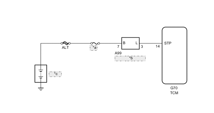
| *a | STOP |
| *b | Stop Light Switch |
| *c | Battery |
PROCEDURE
-
READ VALUE USING INTELLIGENT TESTER (STOP LIGHT SWITCH)
-
Connect the intelligent tester to the DLC3.
-
Turn the ignition switch to ON.
-
Turn the intelligent tester on.
-
Enter the following menus: Powertrain / ECT / Data List / Stop Light Switch.
-
Read the value displayed on the intelligent tester when the brake pedal is depressed and released.
Tester Display Measurement Item/Range Normal Condition Stop Light Switch Stop light switch status/
ON or OFF
-
ON: Brake pedal depressed
-
OFF: Brake pedal released
-
OK 
CHECK FOR INTERMITTENT PROBLEMS Click here
NG 
-
-
CHECK STOP LIGHT SWITCH ASSEMBLY INSTALLATION
-
Check the stop light switch assembly installation Click here.
OK Stop light switch is installed correctly.
NG
SECURELY REINSTALL STOP LIGHT SWITCH ASSEMBLY Click here
OK
-
-
CHECK HARNESS AND CONNECTOR (STOP LIGHT SWITCH - TCM)
-
Disconnect the A85 stop light switch connector.
-
Disconnect the G70 TCM connector.
-
Measure the resistance according to the value(s) in the table below.
Standard Resistance Tester Connection Condition Specified Condition A85-2 (L) - G70-14 (STP) Always Below 1 Ω A85-2 (L) - Body ground Always 10 kΩ or higher G70-14 (STP) - Body ground Always 10 kΩ or higher
NG
REPAIR OR REPLACE HARNESS OR CONNECTOR
OK
-
-
CHECK STOP LIGHT SWITCH ASSEMBLY
-
Check the stop light switch assembly Click here.
OK
REPLACE TCM Click here
NG
REPLACE STOP LIGHT SWITCH ASSEMBLY Click here
-