DYNAMIC RADAR CRUISE CONTROL SYSTEM Cruise Control Switch Circuit
DESCRIPTION
-
The cruise control main switch outputs the cruise control power supply switch signal and each operation switch signal to the ECM.
-
The ECM performs cruise control according to the signal from the cruise control main switch.
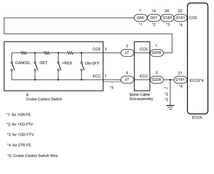
WIRING DIAGRAM
CAUTION / NOTICE / HINT
Note
-
Before replacing the ECM, refer to Service Bulletin.
-
The vehicle is equipped with a Supplemental Restraint System (SRS) which includes components such as airbags. Before servicing (including removal or installation of parts), be sure to read the precaution for Supplemental Restraint System.
PROCEDURE
-
READ VALUE USING GTS
-
Connect the GTS to the DLC3.
-
Turn the ignition switch to ON.
-
Check the Data List for proper functioning of the cruise control switch.
Powertrain > Radar Cruise 1 > Data List
Tester Display Measurement Item Range Normal Condition Diagnostic Note Cancel Switch CANCEL switch status ON or OFF ON: CANCEL switch on
OFF: CANCEL switch off
-SET Switch -SET switch status ON or OFF ON: -SET switch on
OFF: -SET switch off
+RES Switch +RES switch status ON or OFF ON: +RES switch on
OFF: +RES switch off
Cruise Ready Main-CPU Cruise control system standby condition ON or OFF Each time cruise control switch is pushed, ON or OFF changes Cruise Ready Sub-CPU Cruise control system standby condition ON or OFF Each time cruise control switch is pushed, ON or OFF changes OK When the cruise control switch is operated, the display changes as shown above. Result Proceed to OK NG
OK 
PROCEED TO NEXT SUSPECTED AREA SHOWN IN PROBLEM SYMPTOMS TABLE Click here
NG 
-
-
INSPECT CRUISE CONTROL SWITCH
-
Remove the cruise control switch.
-
Inspect the cruise control switch.
Result Proceed to OK NG
NG
REPLACE CRUISE CONTROL SWITCH Click here
OK
-
-
CHECK CRUISE CONTROL SWITCH WIRE
-
Disconnect the z7 spiral cable sub-assembly connector.
-
Disconnect the A cruise control switch wire connector.
-
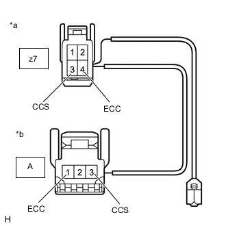
*a Front view of wire harness connector
(to Spiral Cable Sub-assembly)
*b Front view of wire harness connector
(to Cruise Control Switch)
Measure the resistance according to the value(s) in the table below.
Standard Resistance Tester Connection Condition Specified Condition z7-3 (CCS) - A-3 (CCS) Always Below 1 Ω z7-4 (ECC) - A-1 (ECC) Always Below 1 Ω z7-3 (CCS) or A-3 (CCS) - Body ground Always 10 kΩ or higher z7-4 (ECC) or A-1 (ECC) - Body ground Always 10 kΩ or higher Result Proceed to OK NG
NG
REPLACE CRUISE CONTROL SWITCH WIRE
OK
-
-
INSPECT SPIRAL CABLE SUB-ASSEMBLY
-
Remove the spiral cable sub-assembly.
-
Inspect the spiral cable sub-assembly.
Result Proceed to OK NG
NG
REPLACE SPIRAL CABLE SUB-ASSEMBLY Click here
OK
-
-
CHECK HARNESS AND CONNECTOR (SPIRAL CABLE SUB-ASSEMBLY - ECM AND BODY GROUND)
-
Disconnect the G208 spiral cable sub-assembly connector.
-
Disconnect the G56*1, G57*2, G185*3 or G181*4 ECM connector.
-
*1: for 1GR-FE
-
*2: for 1KD-FTV
-
*3: for 1GD-FTV
-
*4: for 2TR-FE
-
-
Measure the resistance according to the value(s) in the table below.
Standard Resistance (for 1GR-FE) Tester Connection Condition Specified Condition G208-1 (CCS) - G56-1 (CCS) Always Below 1 Ω G208-2 (ECC) - Body ground Always Below 1 Ω G208-1 (CCS) or G56-1 (CCS) - Body ground Always 10 kΩ or higher Standard Resistance (for 1KD-FTV) Tester Connection Condition Specified Condition G208-1 (CCS) - G57-14 (CCS) Always Below 1 Ω G208-2 (ECC) - Body ground Always Below 1 Ω G208-1 (CCS) or G56-36 (CCS) - Body ground Always 10 kΩ or higher Standard Resistance (for 1GD-FTV) Tester Connection Condition Specified Condition G208-1 (CCS) - G185-26 (CCS) Always Below 1 Ω G208-2 (ECC) - Body ground Always Below 1 Ω G208-1 (CCS) or G185-26 (CCS) - Body ground Always 10 kΩ or higher Standard Resistance (for 2TR-FE) Tester Connection Condition Specified Condition G208-1 (CCS) - G181-22 (CCS) Always Below 1 Ω G208-2 (ECC) - G181-21 (ECCS) Always Below 1 Ω G208-1 (CCS) or G181-22 (CCS) - Body ground Always 10 kΩ or higher Result Result Proceed to OK (for 1GR-FE, 1KD-FTV, 1GD-FTV) A OK (for 2TR-FE) B NG C
A
REPLACE ECM for 1GR-FE: Click here
REPLACE ECM for 1KD-FTV: Click here
REPLACE ECM for 1GD-FTV: Click hereC
REPAIR OR REPLACE HARNESS OR CONNECTOR
B
-
-
CHECK HARNESS AND CONNECTOR (SPIRAL CABLE SUB-ASSEMBLY - ECM AND BODY GROUND)
-
Disconnect the C153 ECM connector.
-
Measure the resistance according to the value(s) in the table below.
Standard Resistance Tester Connection Condition Specified Condition C153-3 (E1) - Body ground Always Below 1 Ω Result Proceed to OK NG
OK
REPLACE ECM Click here
NG
REPAIR OR REPLACE HARNESS OR CONNECTOR
-