DYNAMIC RADAR CRUISE CONTROL SYSTEM TERMINALS OF ECU
-
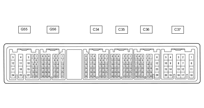
CHECK ECM (for 1GR-FE)
Tech Tips
Each ECM terminal's standard voltage is shown in the table below.
In the table, first follow the information under "Condition". Look under "Terminal No. (Symbol)" for the terminals to be inspected. The standard voltage between the terminals is shown under "Specified Condition".
Use the illustration above as a reference for the ECM terminals.
Terminal No. (Symbol) Wiring Color Terminal Description Condition Specified Condition C36-12 (E1) - Body ground BR - Body ground Ground Always Below 1 Ω C34-22 (D) - C36-12 (E1) B - BR D shift position switch signal Ignition switch ON and shift lever in D, S, "+" or "-" 11 to 14 V Ignition switch ON and shift lever not in D, S, "+" or "-" Below 1 V G55-24 (BATT) - C36-12 (E1) L - BR Battery (for measuring battery voltage and for ECM memory) Always 11 to 14 V G56-9 (SFTD) - C36-12 (E1) LG - BR Down-shift position switch signal Ignition switch ON and shift lever in S 11 to 14 V Ignition switch ON and shift lever in "-" (down-shift) Below 1 V G56-15 (SFTU) - C36-12 (E1) GR - BR Up-shift position switch signal Ignition switch ON and shift lever in S 11 to 14 V Ignition switch ON and shift lever in "+" (up-shift) Below 1 V G56-22 (S) - C36-12 (E1) V - BR S shift position switch signal Ignition switch ON and shift lever in S, "+" or "-" 11 to 14 V Ignition switch ON and shift lever not in S, "+" or "-" Below 1 V G56-1 (CCS) - C36-12 (E1) B - BR Cruise control switch circuit Cruise control main switch off 1 MΩ or higher Cruise control main switch on Below 2.5 Ω +RES switch on 235 to 245 Ω -SET switch on 617 to 643 Ω CANCEL switch on 1509 to 1571 Ω G56-34 (ST1-) - C36-12 (E1) B - BR Stop light switch assembly signal (opposite of voltage at STP terminal) Ignition switch ON,
brake pedal depressed
Below 1.5 V Ignition switch ON,
brake pedal released
7.5 to 14 V G56-35 (STP) - C36-12 (E1) V - BR Stop light switch assembly signal Brake pedal depressed 7.5 to 14 V Brake pedal released Below 1.5 V -
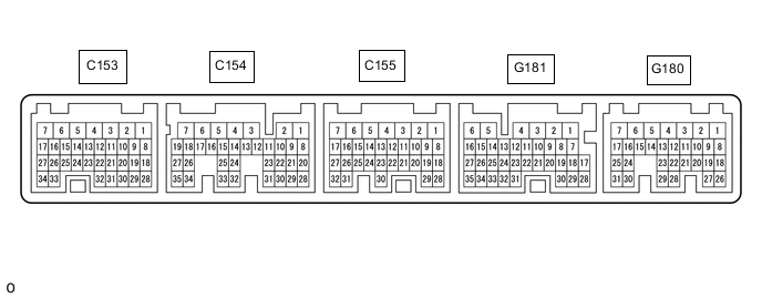
CHECK ECM (for 2TR-FE)
Tech Tips
Each ECM terminal's standard voltage is shown in the table below.
In the table, first follow the information under "Condition". Look under "Terminal No. (Symbol)" for the terminals to be inspected. The standard voltage between the terminals is shown under "Specified Condition".
Use the illustration above as a reference for the ECM terminals.
Terminal No. (Symbol) Wiring Color Terminal Description Condition Specified Condition C153-3 (E1) - Body ground BR - Body ground Ground Always Below 1 Ω C155-17 (SFTU) - C153-3 (E1) GR- BR Down-shift switch signal Ignition switch ON and shift lever in S 11 to 14 V Ignition switch ON and shift lever in "+" (up-shift) Below 1 V Ignition switch ON and "+" shift paddle operated (up-shift) C155-27 (SFTD) - C153-3 (E1) LG - BR Up-shift switch signal Ignition switch ON and shift lever in S 11 to 14 V Ignition switch ON and shift lever in "-" (down-shift) Below 1 V Ignition switch ON and "-" shift paddle operated (down-shift) C155-30 (S) - C153-3 (E1) V - BR S shift position switch signal Ignition switch ON and shift lever in S, "+" or "-" 11 to 14 V Ignition switch ON and shift lever not in S, "+" or "-" Below 1 V G181-18 (D) - C153-3 (E1) B - BR D shift position signal Ignition switch ON and shift lever in D, S, "+" or "-" 11 to 14 V Ignition switch ON and shift lever not in D, S, "+" or "-" Below 1 V G181-22 (CCS) - G181-21 (ECCS) B - BR Cruise control main switch circuit Cruise control switch off 1 MΩ or higher Cruise control switch on Below 2.5 Ω +RES switch on 235 to 245 Ω -SET switch on 617 to 643 Ω CANCEL switch on 1509 to 1571 Ω G180-3 (BATT) - C153-3 (E1) L - BR Battery (for measuring battery voltage and for ECM memory) Always 11 to 14 V G180-10 (STP) - C153-3 (E1) V - BR Stop light switch assembly signal Brake pedal depressed 7.5 to 14 V Brake pedal released 0 to 1.5 V G180-11 (ST1-) - C153-3 (E1) B - BR Stop light switch assembly signal (opposite to voltage at STP terminal) Ignition switch ON, brake pedal depressed 0 to 1.5 V Ignition switch ON, brake pedal released 7.5 to 14 V -
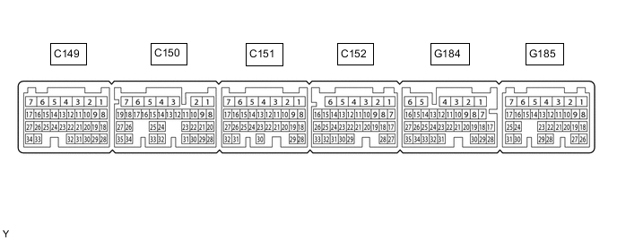
CHECK ECM (for 1GD-FTV)
Tech Tips
Each ECM terminal's standard voltage is shown in the table below.
In the table, first follow the information under "Condition". Look under "Terminal No. (Symbol)" for the terminals to be inspected. The standard voltage between the terminals is shown under "Specified Condition".
Use the illustration above as a reference for the ECM terminals.
Terminal No. (Symbol) Wiring Color Terminal Description Condition Specified Condition C149-14 (D) - C152-1 (E1) B - W-B D shift position signal Ignition switch ON and shift lever in D, S, "+" or "-" 11 to 14 V Ignition switch ON and shift lever not in D, S, "+" or "-" Below 1 V C152-1 (E1) - Body ground W-B - Body ground Ground Always Below 1 Ω G184-13 (S) - C152-1 (E1) V - W-B S shift position switch signal Ignition switch ON and shift lever in S, "+" or "-" 11 to 14 V Ignition switch ON and shift lever not in S, "+" or "-" Below 1 V G184-20 (SFTD) - C152-1 (E1) LG - W-B Down-shift switch signal Ignition switch ON and shift lever in S 11 to 14 V Ignition switch ON and shift lever in "-" (down-shift) Below 1 V G184-21 (SFTU) - C152-1 (E1) GR - W-B Up-shift switch signal Ignition switch ON and shift lever in S 11 to 14 V Ignition switch ON and shift lever in "+" (up-shift) Below 1 V G185-1 (BATT) - C152-1 (E1) L - W-B Battery (for measuring battery voltage and for ECM memory) Always 11 to 14 V G185-12 (ST1-) - C152-1 (E1) B - W-B Stop light switch assembly signal
(opposite to voltage at STP terminal)
Ignition switch ON,
brake pedal depressed
0 to 1.5 V Ignition switch ON,
brake pedal released
7.5 to 14 V G185-13 (STP) - C152-1 (E1) V - W-B Stop light switch assembly signal Brake pedal depressed 7.5 to 14 V Brake pedal released 0 to 1.5 V G185-26 (CCS) - C152-1 (E1) B - W-B Cruise control switch circuit Cruise control main switch off 1 MΩ or higher Cruise control main switch on Below 2.5 Ω +RES switch on 235 to 245 Ω -SET switch on 617 to 643 Ω CANCEL switch on 1509 to 1571 Ω -
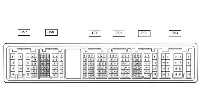
CHECK ECM (for 1KD-FTV)
Tech Tips
Each ECM terminal's standard voltage is shown in the table below.
In the table, first follow the information under "Condition". Look under "Terminal No. (Symbol)" for the terminals to be inspected. The standard voltage between the terminals is shown under "Specified Condition".
Use the illustration above as a reference for the ECM terminals.
Terminal No. (Symbol) Wiring Color Terminal Description Condition Specified Condition C93-1 (E1) - Body ground BR - Body ground Ground Always Below 1 Ω G57-23 (BATT) - C93-1 (E1) L - BR Battery (for measuring the battery voltage and for the ECM memory) Always 11 to 14 V G57-9 (ST1-) - C93-1 (E1) B - BR Stop light switch assembly signal
(opposite to voltage at STP terminal)
Ignition switch ON,
brake pedal depressed
0 to 1.5 V Ignition switch ON,
brake pedal released
7.5 to 14 V G57-8 (STP) - C93-1 (E1) V - BR Stop light switch assembly signal Brake pedal depressed 7.5 to 14 V Brake pedal released 0 to 1.5 V G57-14 (CCS) - C93-1 (E1) B - BR Cruise control switch circuit Cruise control main switch off 1 MΩ or higher Cruise control main switch on Below 2.5 Ω +RES switch on 235 to 245 Ω -SET switch on 617 to 643 Ω CANCEL switch on 1509 to 1571 Ω -
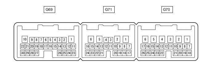
CHECK TCM (for 1KD-FTV)
Tech Tips
Each TCM terminal's standard voltage is shown in the table below.
In the table, first follow the information under "Condition". Look under "Terminal No. (Symbol)" for the terminals to be inspected. The standard voltage between the terminals is shown under "Specified Condition".
Use the illustration above as a reference for the TCM terminals.
Terminal No. (Symbol) Wiring Color Terminal Description Condition Specified Condition G71-8 (D) - G69-1 (E1) B - BR D shift position switch signal Ignition switch ON and shift lever in D, S, "+" or "-" 11 to 14 V Ignition switch ON and shift lever not in S, "+" or "-" Below 1 V G69-1 (E1) - Body ground BR - Body ground Ground Always Below 1 Ω G70-15 (S) - G69-1 (E1) V - BR S shift position switch signal Ignition switch ON and shift lever in S, "+" or "-" 11 to 14 V Ignition switch ON and shift lever not in S, "+" or "-" Below 1 V G70-22 (SFTU) - G69-1 (E1) GR - BR Up-shift position switch signal Ignition switch ON and shift lever in S 11 to 14 V Ignition switch ON and shift lever in "+" position (up-shift) Below 1 V G70-23 (SFTD) - G69-1 (E1) LG - BR Down-shift position switch signal Ignition switch ON and shift lever in S 11 to 14 V Ignition switch ON and shift lever in "-" (down-shift) Below 1 V -
CHECK DRIVING SUPPORT ECU ASSEMBLY

Terminal No. (Symbol) Wiring Color Terminal Description Condition Specified Condition G224-3 (BZ) - G224-28 (GND) SB - W-B Skid control buzzer output Ignition switch ON, buzzer not sounding 11 to 14 V G224-7 (B) - G224-28 (GND) G - W-B Power source Ignition switch ON 10.5 to 16 V G224-8 (CA1P) - G224-28 (GND) GR - W-B CAN communication signal Ignition switch ON Pulse generation
(See waveform 1)
G224-9 (CA1N) - G224-28 (GND) W - W-B CAN communication signal Ignition switch ON Pulse generation
(See waveform 2)
G224-10 (CA2H) - G224-28 (GND) G - W-B CAN communication signal Ignition switch ON Pulse generation
(See waveform 1)
G224-11 (CA2L) - G224-28 (GND) W - W-B CAN communication signal Ignition switch ON Pulse generation
(See waveform 2)
G224-23 (SPSW) - G224-28 (GND) V - W-B Steering pad switch signal (Vehicle-to-vehicle distance control switch signal) Ignition switch ON, vehicle-to-vehicle distance control switch on Below 1 Ω Ignition switch ON, vehicle-to-vehicle distance control switch off 4.75 to 5.25 V G224-28 (GND) - Body ground W-B - Body ground Ground Always Below 1 Ω
-
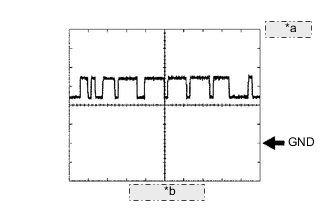
*a 1 V/DIV. *b 10 μsec./DIV. Waveform 1
-
CAN communication signal
Item Content Terminal Name Between G224-8 (CA1P) and G224-28 (GND)
Between G224-10 (CA2H) and G224-28 (GND)
Tester Range 1 V/DIV., 10 μsec./DIV. Condition Ignition switch ON Tech Tips
The waveform varies depending on the CAN communication signal.
-
-

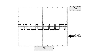
*a 1 V/DIV. *b 10 μsec./DIV. Waveform 2
-
CAN communication signal
Item Content Terminal Name Between G224-9 (CA1N) and G224-28 (GND)
Between G224-11 (CA2L) and G224-28 (GND)
Tester Range 1 V/DIV., 10 μsec./DIV. Condition Ignition switch ON Tech Tips
The waveform varies depending on the CAN communication signal.
-
-
-
CHECK MILLIMETER WAVE RADAR SENSOR

Terminal No. (Symbol) Wiring Color Terminal Description Condition Specified Condition A100-1 (SGND) - Body ground BR - Body ground Ground Always Below 1 Ω A100-2 (CA2L) - A100-1 (SGND) W - BR CAN communication signal Ignition switch ON Pulse generation
(See waveform 2)
A100-3 (CA2H) - A100-1 (SGND) V - BR CAN communication signal Ignition switch ON Pulse generation
(See waveform 1)
A100-5 (CA1P) - A100-1 (SGND) L - BR CAN communication signal Ignition switch ON Pulse generation
(See waveform 1)
A100-6 (CA1N) - A100-1 (SGND) W - BR CAN communication signal Ignition switch ON Pulse generation
(See waveform 2)
A100-8 (IGB) - A100-1 (SGND) GR-G - BR Power source Ignition switch ON 10.5 to 16 V
-

*a 1 V/DIV. *b 10 μsec./DIV. Waveform 1
-
CAN communication signal
Item Content Terminal Name Between A100-3 (CA2H) and A100-1 (SGND)
Between A100-5 (CA1P) and A100-1 (SGND)
Tester Range 1 V/DIV., 10 μsec./DIV. Condition Ignition switch ON Tech Tips
The waveform varies depending on the CAN communication signal.
-
-
*a 1 V/DIV. *b 10 μsec./DIV. Waveform 2
-
CAN communication signal
Item Content Terminal Name Between A100-2 (CA2L) and A100-1 (SGND)
Between A100-6 (CA1N) and A100-1 (SGND)
Tester Range 1 V/DIV., 10 μsec./DIV. Condition Ignition switch ON Tech Tips
The waveform varies depending on the CAN communication signal.
-
-