CRUISE CONTROL SYSTEM TC and CG Terminal Circuit
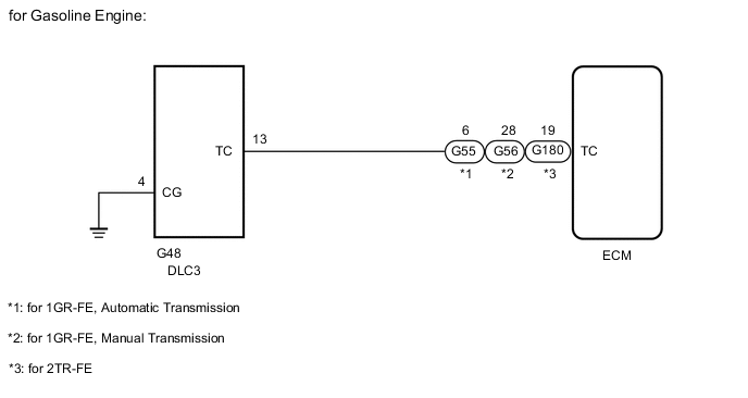
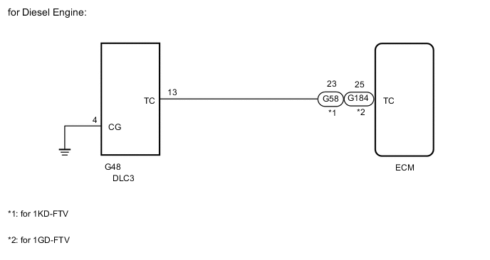
WIRING DIAGRAM
PROCEDURE
-
CHECK HARNESS AND CONNECTOR (DLC3 - ECM AND BODY GROUND)
-
Disconnect the G55*1, G56*2, G58*3, G180*4 or G184*5 ECM connector.
-
*1: for 1GR-FE, Automatic Transmission
-
*2: for 1GR-FE, Manual Transmission
-
*3: for 1KD-FTV
-
*4: for 2TR-FE
-
*5: for 1GD-FTV
-
-
Measure the resistance according to the value(s) in the table below.
Standard Resistance for 1GR-FE, Automatic Transmission Tester Connection Condition Specified Condition G48-13 (TC) - G55-6 (TC) Always Below 1 Ω G48-4 (CG) - Body ground G48-13 (TC) - Body ground Always 10 kΩ or higher for 1GR-FE, Manual Transmission Tester Connection Condition Specified Condition G48-13 (TC) - G56-28 (TC) Always Below 1 Ω G48-4 (CG) - Body ground G48-13 (TC) - Body ground Always 10 kΩ or higher for 1KD-FTV Tester Connection Condition Specified Condition G48-13 (TC) - G58-23 (TC) Always Below 1 Ω G48-4 (CG) - Body ground G48-13 (TC) - Body ground Always 10 kΩ or higher for 2TR-FE Tester Connection Condition Specified Condition G48-13 (TC) - G180-19 (TC) Always Below 1 Ω G48-4 (CG) - Body ground G48-13 (TC) - Body ground Always 10 kΩ or higher for 1GD-FTV Tester Connection Condition Specified Condition G184-25 (TC) - G58-23 (TC) Always Below 1 Ω G48-4 (CG) - Body ground G48-13 (TC) - Body ground Always 10 kΩ or higher
OK 
PROCEED TO NEXT SUSPECTED AREA SHOWN IN PROBLEM SYMPTOMS TABLE Click here
NG
REPAIR OR REPLACE HARNESS OR CONNECTOR
-